3
IDK-1119R User Manual
Chapter 1
O
verview
1.3
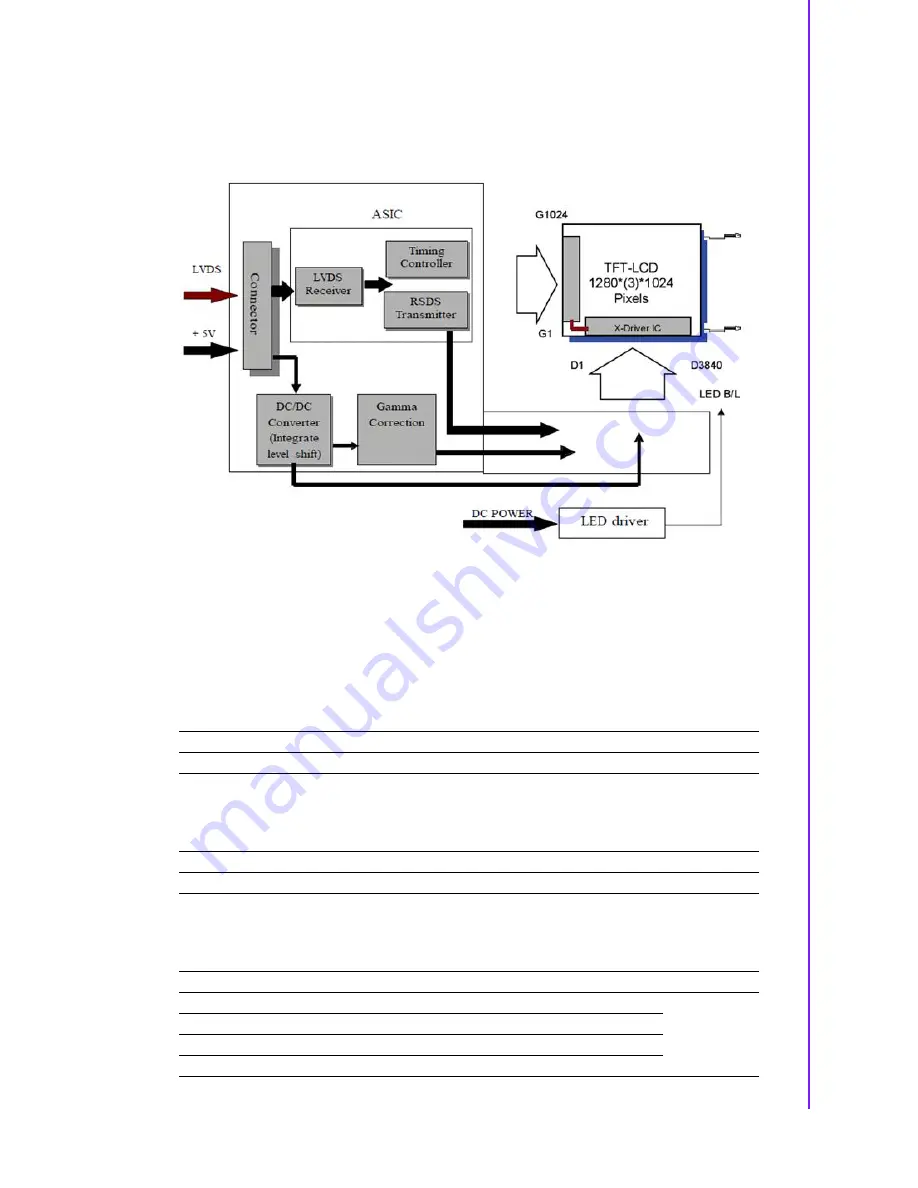
Functional Block Diagram
The following diagram shows the functional block of the 19 inches Color TFT-LCD
Module:
Figure 1.1 Function block diagram
1.4
Absolute Maximum Ratings
Absolute maximum ratings of the module is as following:
1.4.1
Absolute Ratings of TFT LCD Module
1.4.2
Absolute Ratings of Backlight Unit
1.4.3
Absolute Ratings of Environment
Note1:
With in Ta= 25°C and no condensation
Item
Symbol
Min.
Max.
Unit
Conditions
Logic/LCD Drive Voltage
Vin
0.3
+5.5
[Volt]
Note 1, 2
Item
Symbol
Min.
Max.
Unit
Conditions
LED Light Bar Current
ILed
-
1.25
[A]rms
Note 1, 2
Item
Symbol
Min.
Max.
Unit
Conditions
Operating Temperature
TOP
0
+50
[oC]
Note 3
Operation Humidity
HOP
5
90
[%RH]
Storage Temperature
TST
-20
+60
[oC]
Storage Humidity
HST
5
90
[%RH]
Summary of Contents for IDK-1119R-35SXA1E
Page 1: ...User Manual IDK 1119R 35SXA1E TFT LCD 19 SXGA LED Backlight ...
Page 7: ...Chapter 1 1 Overview ...
Page 11: ...5 IDK 1119R User Manual Chapter 1 Overview 1 5 2 Rear View ...
Page 12: ...IDK 1119R User Manual 6 ...
Page 13: ...Chapter 2 2 Electrical Characteristics ...
Page 16: ...IDK 1119R User Manual 10 ...
Page 17: ...Chapter 3 3 Signal Characteristics ...
Page 22: ...IDK 1119R User Manual 16 T6 0 ms T7 10 ms T8 100 T9 0 16 50 T10 T11 1000 ...
Page 23: ...Chapter 4 4 Connector Pin Assignment ...
Page 26: ...IDK 1119R User Manual 20 ...
Page 27: ...Chapter 5 5 Touch Screen ...
Page 30: ...IDK 1119R User Manual 24 ...
Page 31: ...Chapter 6 6 Touch Controller ...
Page 35: ...Appendix A A OpticalCharacteristics ...
Page 38: ...IDK 1119R User Manual 32 ...


