background image

v

IPC-3012 User Manual

/ 用户手册


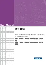
每台激光产品根据下列各条要求带有标记。在激光产品的使用、维护或检修期
间,标记按其目的必须永久固定,字迹清晰,明显可见。标记应放置在人员不会
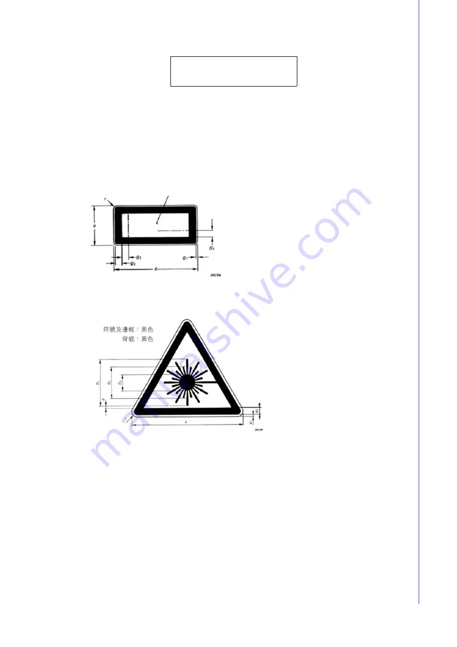
受到超过 1 类 AEL 的激光辐射照射就能看到的位置。标记的边框及符号应在黄底
面上涂成黑色,但 1 类激光器不必用此颜色组合。

如果激光产品的尺寸或设计不可能使产品上有标记,则建议标记附在使用说明书
中或包装箱上。

说明标记
均要有此标记

警告标记 - 危险符号
除 1 和 1M 类,均要有

18.

本设备符合 FCC 规则第 15 款的规定。操作受如下两个条件限制:
(1) 本设备不得产生有害的干扰,而且 
(2) 本设备必须能经受干扰,包括可能引起意外操作的干扰。

19.

注意:无论何时进行操作,请务必完全断开机箱电源。不可在电源接通时进行设
备连接,以避免瞬间电涌损坏敏感电子元件。只有专业技术人员才可以打开机
箱。

20.

注意:接触产品的母板、底板或附加卡前,请先确保您接地来移除身上附带的静
电。由于现在的电子设备对静电十分敏感,为了安全起见,请使用接地腕环。请
将所有电子元件放在无静电的表面或静电屏蔽袋中。

21.

注意:未经专业认可的元件会损坏设备。请使用附件盒中提供的元件 (如螺丝)
以确保正确的安装。

22.

本产品不带电源线销售,用户需购买符合 CCC 要求的电源线。

CLASS I LASER PRODUCT

KLASS I LASER PRODUKT

Summary of Contents for IPC-3012

Page 1: ...User Manual IPC 3012 Compact Embedded Chassis for PICMG 1 3 Half Size SHB PICMG 1 3 SHB PICMG 1 3 SHB...

Page 2: ...ans without the prior written permission of Advantech Co Ltd Information provided in this manual is intended to be accurate and reliable How ever Advantech Co Ltd assumes no responsibility for its use...

Page 3: ...All cautions and warnings on the equipment should be noted 12 If the equipment is not used for a long time disconnect it from the power source to avoid damage by transient overvoltage 13 Never pour an...

Page 4: ...nents can be damaged by sudden power surges 20 CAUTION Always ground yourself to remove any static charge before touching the motherboard backplane or add on cards Modern electronic devices are very s...

Page 5: ...v IPC 3012 User Manual 1 AEL 1 1 1M 18 FCC 15 1 2 19 20 21 22 CCC CLASS I LASER PRODUCT KLASS I LASER PRODUKT...

Page 6: ...IPC 3012 User Manual vi 1 2 3 4 5 6 7 0 C 32 F 40 C 104 F 8 9 10 11 12 13 14 15 16 17 IEC 60825 18 FCC 15 1 2 19 20 21 CLASS I LASER PRODUCT KLASS I LASER PRODUKT...

Page 7: ...best performance possible from your products If you run into technical difficulties we are here to help For the most frequently asked questions you can easily find answers in your product documentati...

Page 8: ...ials service time and freight Please consult your dealer for more details If you think you have a defective product follow these steps 1 Collect all the information about the problem encountered For e...

Page 9: ...sales repre sentative immediately We have carefully inspected the IPC 3012 mechanically and electrically before shipment It should be free of marks and scratches and in perfect working order upon rece...

Page 10: ...IPC 3012 User Manual x IPC 3012 CPU IPC 3012 IPC 3012...

Page 11: ...e 2 2 Install CPU board Backplane CPU cooler CPU CPU CPU CPU 7 2 3 Installing Internal 2 5 HDD into Drive Bay 2 5 2 5 HDD 8 Figure 2 3 Installing Internal 3 5 HDD 5 25 ODD into Drive Bay 3 5 5 25 HDD...

Page 12: ...IPC 3012 User Manual xii 15 A 1 Exploded Diagram Parts List 16 Figure A 1 Exploded Diagram 16 Table A 1 Part List 17...

Page 13: ...Chapter 1 1 General Information...

Page 14: ...l with filter Weight 3 24 kg 7 14 lb Dimensions 232 W x 90 H x 232 D mm 2 x 2 5 HDD LED HDD 2 x 6 cm 27 CFM 3 24 kg 7 14 lb 232 W x 90 H x 232 D mm 2 x 2 5 HDD LED HDD 2 x 6 cm 27 CFM 9 96 kg 21 93 lb...

Page 15: ...3 IPC 3012 User Manual Chapter 1 General Information 1 3 Dimension Diagram Figure 1 1 Dimension Diagram Unit mm inch...

Page 16: ...IPC 3012 User Manual 4...

Page 17: ...Chapter 2 2 System Setup...

Page 18: ...IPC 3012 User Manual 6 2 1 Removing Top Cover Figure 2 1 Removing Side Cover...

Page 19: ...7 IPC 3012 User Manual Chapter 2 System Setup 2 2 Install CPU board Backplane CPU cooler CPU CPU 1 1 CPU CPU Figure 2 2 Install CPU board Backplane CPU cooler CPU CPU CPU CPU...

Page 20: ...IPC 3012 User Manual 8 2 3 Installing Internal 2 5 HDD into Drive Bay 2 5 2 5 HDD Figure 2 3 Installing Internal 3 5 HDD 5 25 ODD into Drive Bay 3 5 5 25 HDD...

Page 21: ...9 IPC 3012 User Manual Chapter 2 System Setup 2 4 Installing Add On Card Figure 2 4 Installing the Motherboard Add On Card...

Page 22: ...ser Manual 10 2 5 Installing Wallmount Bracket Figure 2 5 Installing Wallmount Bracket Note This pair of wallmount bracket is designed for side of chassis and bot tom side Reverse installation is not...

Page 23: ...Chapter 3 3 Operation...

Page 24: ...IPC 3012 User Manual 12 3 1 Change Fan and Filter module Figure 3 1 Change Fan and Filter module...

Page 25: ...13 IPC 3012 User Manual Chapter 3 Operation 3 2 Changing Power Supply Figure 3 2 Changing Power Supply...

Page 26: ...IPC 3012 User Manual 14...

Page 27: ...Appendix A A Exploded Diagram Parts List...

Page 28: ...IPC 3012 User Manual 16 A 1 Exploded Diagram Parts List Figure A 1 Exploded Diagram...

Page 29: ...LD DOWN BAR BRACKET 3 POWER BUTTON 15 HOLD DOWN SUPPORT BRACKET 4 BOTTOM CHASSIS 16 ADD ON CARD FIXED RUBBER 5 POWER SUPPLY 17 I O BRACKET I O 6 FRONT I O USB CABLE I O USB I O USB 18 SYSTEM FAN 7 BAC...

Page 30: ...e No part of this publication may be reproduced in any form or by any means electronic photocopying recording or otherwise without prior written permis sion of the publisher All brand and product name...

Reviews: