


IPC-603MB User Manual
6
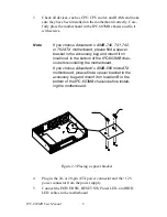
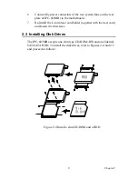
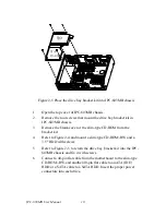
Chapter 2 System Setup
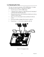
The following procedures are provided to assist you in installing a moth-
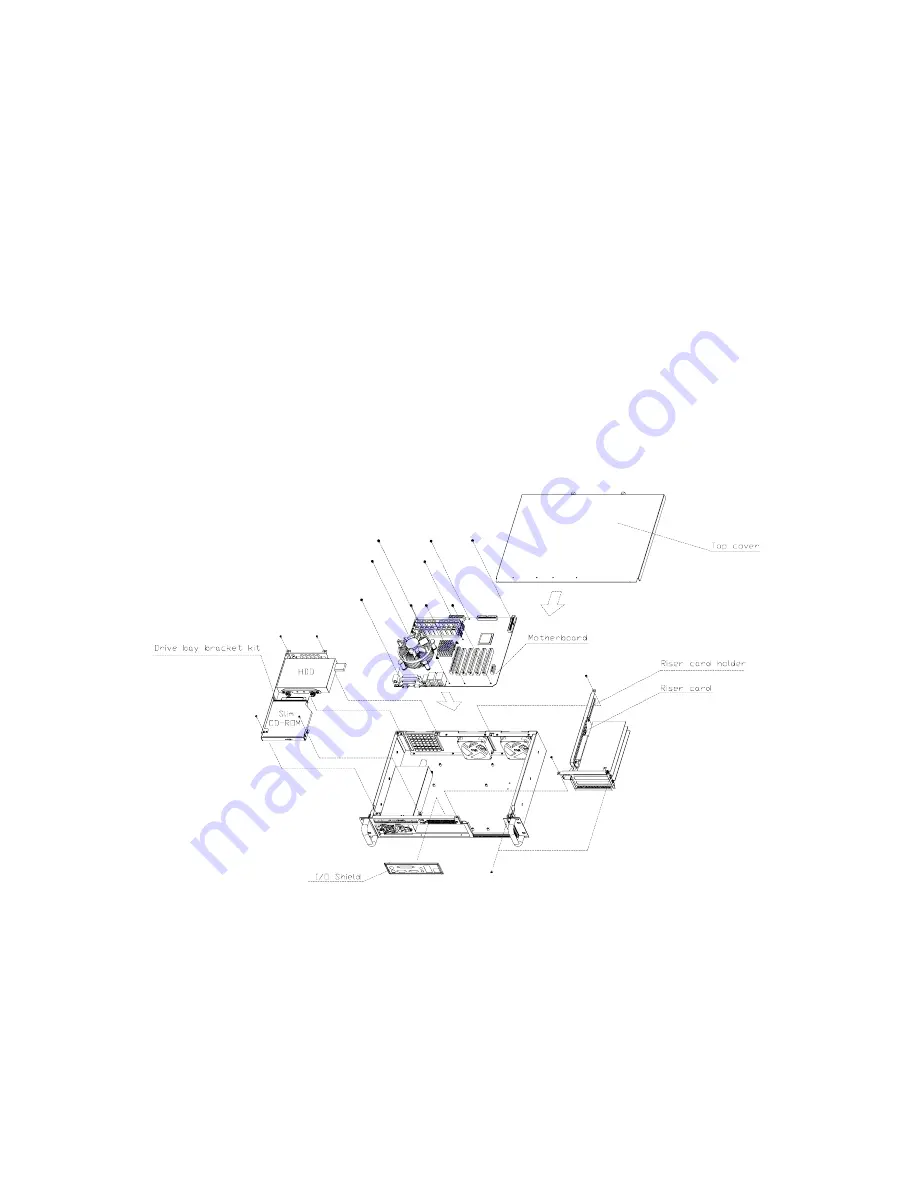
erboard, drives, and add-in cards into an IPC-603MB chassis. Refer to
Appendix A, Exploded Diagram, for the names of each part used in this
manual.
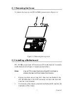
Figure 2-1 System setup
Note
Figure 2-1 is the summary illustration for install-
ing the whole IPC-603MB system. To shorten the
total system installation time, we suggest users
to install a motherboard first, then the riser card
and add-in card(s), and finally, the drive bay.
Summary of Contents for IPC-603MB
Page 1: ...IPC 603MB Ultra Compact 2U high Rack mount IPC Chassis User Manual...
Page 10: ...IPC 603MB User Manual x...
Page 11: ...2 CHAPTER 1 General Information...
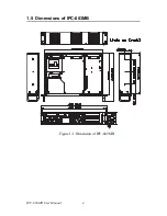
Page 14: ...IPC 603MB User Manual 4 1 5 Dimensions of IPC 603MB Figure 1 1 Dimension of IPC 603MB...
Page 15: ...2 CHAPTER 2 System Setup...
Page 22: ...IPC 603MB User Manual 12...
Page 23: ...2 CHAPTER 3 Operation...
Page 29: ...2 APPENDIX A Exploded Diagram...
Page 30: ...IPC 603MB User Manual 20 Appendix A Exploded Diagram...


