


IPC-603MB User Manual
8
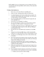
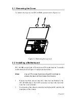
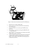
3.
Check all devices, such as CPU, CPU cooler, and RAMs and make
sure they have been installed on the motherboard correctly. Care-
fully place the motherboard in the IPC-603MB chassis and fix it
with screws.
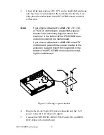
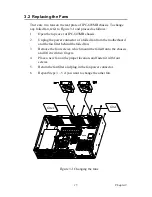
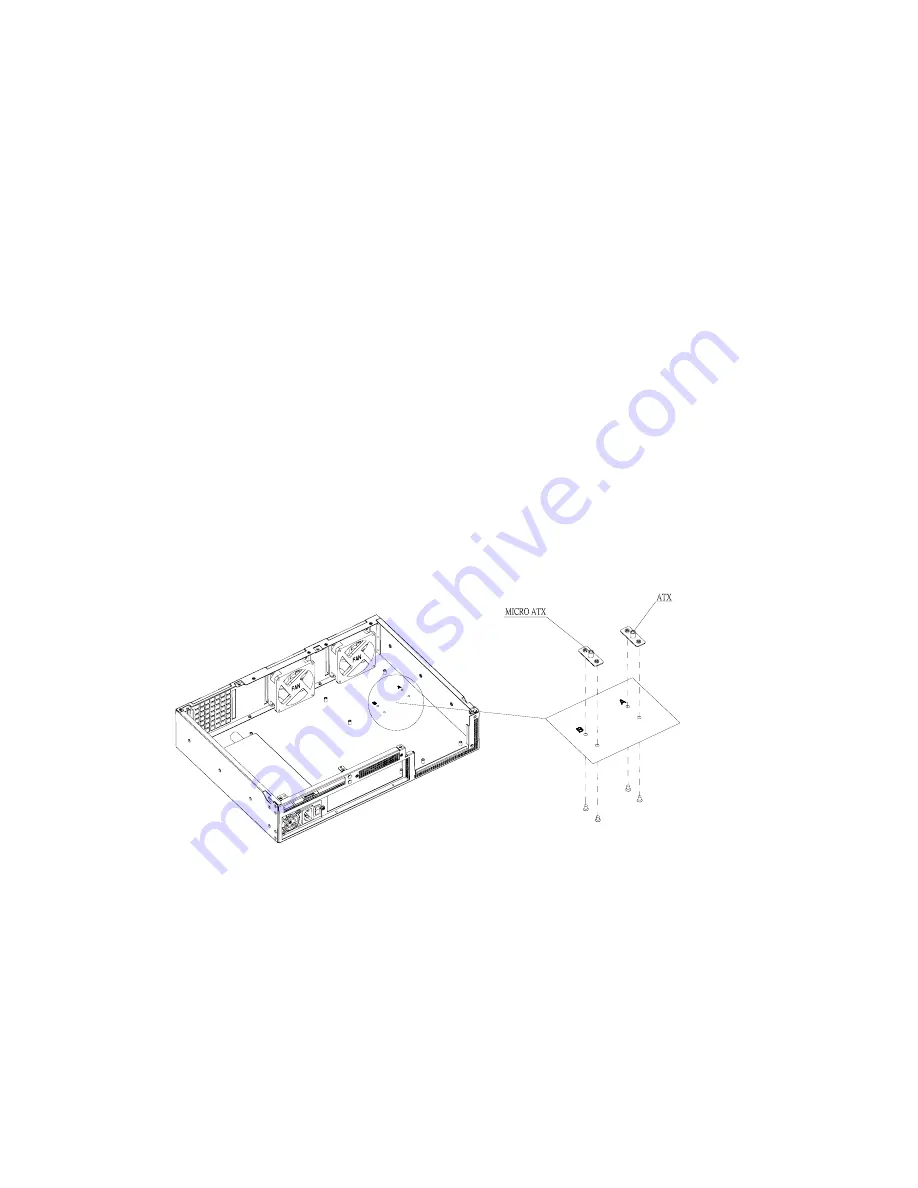
Figure 2-3 Placing a spacer bracket
4.
Plug in the 24- or 20-pin ATX power connector and the +12 V
power connector from the power supply.
5.
Connect the POWER SW, RESET SW, Power LED, and HDD
LED cables to the motherboard.
Note
If you choose Advantech’s AIMB-740, 741, 742,
or 762 ATX motherboard, please find a spacer
bracket in the accessory bag and mount it on
location A in the bottom of the IPC-603MB chas-
sis before installing the motherboard.
If you choose Advantech’s AIMB-560 microATX
motherboard, please find a spacer bracket in the
accessory bag and mount it on location B in the
bottom of the IPC-603MB chassis before install-
ing the motherboard.
Summary of Contents for IPC-603MB
Page 1: ...IPC 603MB Ultra Compact 2U high Rack mount IPC Chassis User Manual...
Page 10: ...IPC 603MB User Manual x...
Page 11: ...2 CHAPTER 1 General Information...
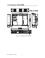
Page 14: ...IPC 603MB User Manual 4 1 5 Dimensions of IPC 603MB Figure 1 1 Dimension of IPC 603MB...
Page 15: ...2 CHAPTER 2 System Setup...
Page 22: ...IPC 603MB User Manual 12...
Page 23: ...2 CHAPTER 3 Operation...
Page 29: ...2 APPENDIX A Exploded Diagram...
Page 30: ...IPC 603MB User Manual 20 Appendix A Exploded Diagram...


