
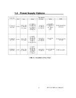
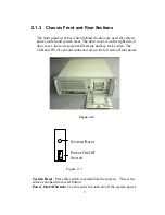

2.1.3 Chassis Front and Rear Sections
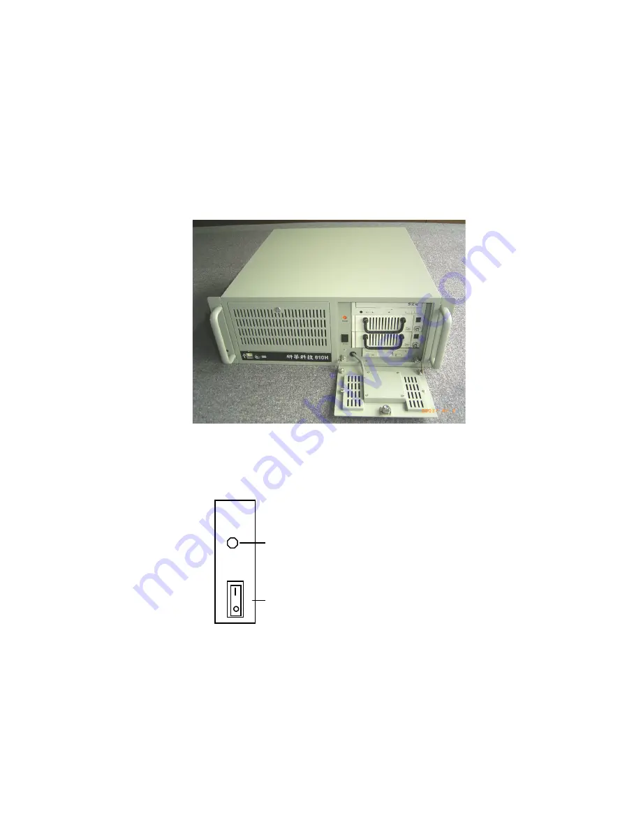
The front panel switches which behind the door are used for system
power switch and system reset. The door cover is on the right side of
door cover, there are system LED status and key lock switch. The
USB and P/S 2 keyboard connector are on the left side of front panel.
Figure 2-2
Power On/Off
Switch
System Reset
Figure 2-3
System Reset
: Press this switch to reinitialize the system. This is the
same as the hardware reset button.
Power On/Off Switch:
Use this switch to turn on/off the system power.
9
Summary of Contents for IPC-610-H
Page 1: ...IPC 610 H 4U Rackmount Chassis User s Manual...
Page 6: ......
Page 7: ...General Information 1 CHAPTER...
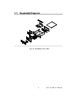
Page 12: ...1 7 Exploded Diagram Fig 1 2 Installation Flow Chart IPC 610 H User s Manual 6...
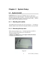
Page 13: ...System Setup 2 CHAPTER...
Page 22: ......
Page 23: ...Backplane A APPENDIX...


