background image

IPC-610F  User's Manual

5

Chapter 2  System Setup

Setting up your IPC-610F requires only a screwdriver and a small amount of time. Before you begin,
you should also gather together all of the cards you plan to install, as well as the keyboard you plan to
use.

A lockable door is located on the chassis front cover, providing access to the control panel. This offers
protection and security against damage and unauthorized access. The control panel functions include
power on/off, keyboard lock, reset switch and three LED indicators (power on, keyboard lock and
HDD) to assist in monitoring system status. On the rear panel there is a grounding point (earthing
point) located on the bottom right hand corner. This provides an earth for the whole system and is
attached via a screw.

WARNINGDisconnect all power from the chassis before you install the CPU cards. Unplug

the power cord from the wall; turning off the power switch alone is not sufficient. If
you are not sure what to do, take the job to an experienced professional.

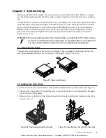
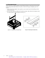
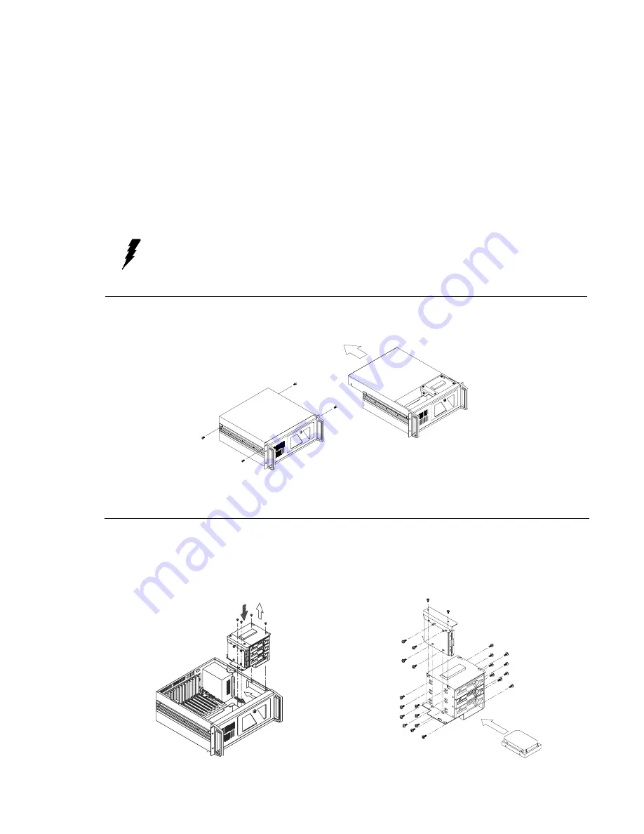
2.1  Removing the Cover

There are screws which secure the cover to the chassis. They are along the sides, near the top. Re-
move them, and then slide the cover to the rear of the chassis. See Fig. 2-1 below:

Figure 2-1: Removing the cover

2.2  Adding Your Disk Drives

1. Remove the four outer screws which mount the shock-resistant drive-bay to the chassis. (See Fig. 2-2)

2. Slide the drive bay about 2 cm toward the rear, to a location where it is not obstructed by the upper

rim. Lift it free of the chassis.

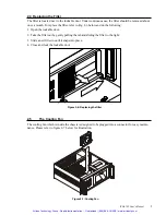
3. Remove the cover to the drive bay front and insert the drives into their proper locations in the drive

bay. (See Fig. 2-3)

Figure 2-2: Inserting/removing the drive bay

Figure 2-3: Inserting the drives into the drive bay

Artisan Technology Group - Quality Instrumentation ... Guaranteed | (888) 88-SOURCE | www.artisantg.com

Summary of Contents for IPC-610BP-30XF

Page 1: ...ss underutilized and idle equipment along with credit for buybacks and trade ins Custom engineering so your equipment works exactly as you specify Critical and expedited services Leasing Rentals Demos...

Page 2: ...IPC 610F Industrial PC Chassis Artisan Technology Group Quality Instrumentation Guaranteed 888 88 SOURCE www artisantg com...

Page 3: ...r Advantech Co Ltd assumes no respon sibility for its use nor for any infringements of the rights of third parties which may result from its use Acknowledgments IPC 610F PCA 6113P4R PCA 6114 PCA 6114P...

Page 4: ...nstalling the power supply and changing the rear cover and window 8 Appendix A Passive Backplanes 9 A 1 PCA 6114 14 slot ISA bus backplane 9 A 2 PCA 6114P4 B 9 ISA 4 PCI 1 CPU slot Backplane 10 A 3 PC...

Page 5: ...Appendix C Safety Instructions 17 C 1 English 17 C 2 German Wichtige Sicherheishinweise 18 Artisan Technology Group Quality Instrumentation Guaranteed 888 88 SOURCE www artisantg com...

Page 6: ...by two filtered push pull cooling fans to exclude dust and dirt A lockable door protects drives and switches from tampering and foreign particles 1 2 Model List 1 3 Specifications General Constructio...

Page 7: ...ating temperature 0 50 C 32 122 F Relative humidity 10 95 40 C non condensing Vibration operating Random Vibration 5 500 Hz 1 G RMS Shock operating 10 G acceleration peak 11 ms duration Safety C UL ap...

Page 8: ...IPC 610F User s Manual 3 42 6 50 43 8 50 48 2 00 173 IPC 610BP 30XF 1 4 Dimensions Artisan Technology Group Quality Instrumentation Guaranteed 888 88 SOURCE www artisantg com...

Page 9: ...4 IPC 610F User s Manual 48 2 00 438 50 426 50 173 IPC 610MB 30XF Artisan Technology Group Quality Instrumentation Guaranteed 888 88 SOURCE www artisantg com...

Page 10: ...assis before you install the CPU cards Unplug the power cord from the wall turning off the power switch alone is not sufficient If you are not sure what to do take the job to an experienced profession...

Page 11: ...lows 1 Detach the hold down clamp by removing the two screws located at each end and lifting it off the chassis See Fig 2 4 2 Insert the rubber buffers provided into the hold down clamp These buffers...

Page 12: ...out by gently pulling the tab and sliding the filter to the right 3 Slide a new filter in until it snaps into place 4 Close and lock the lockable door Figure 2 6 Replacing the filter 2 5 The Cooling F...

Page 13: ...C 610F with backplane version Figure 2 9 IPC 610F with motherboard version 2 6 Installing the power supply and changing the rear cover and window Artisan Technology Group Quality Instrumentation Guara...

Page 14: ...gnals Resistor Signals RN2 SA7 SA10 RP1 SMEMW SMEMR IOW IOR RN5 SA15 SA8 RN3 SBHE LA23 LA17 RN4 SD0 SD7 RN1 LA19 LA16 RN6 SD8 SD15 Appendix A Passive Backplanes A 1 PCA 6114 14 slot ISA bus backplane...

Page 15: ...10 IPC 610F User s Manual A 2 PCA 6114P4 B 9 ISA 4 PCI 1 CPU slot Backplane Dimensions 260 x 315 mm Unit mm Artisan Technology Group Quality Instrumentation Guaranteed 888 88 SOURCE www artisantg com...

Page 16: ...IPC 610F User s Manual 11 A 3 PCA 6114P7 6 ISA 7 PCI 1 CPU slot Backplane Dimensions 300 x 323 mm Unit mm Artisan Technology Group Quality Instrumentation Guaranteed 888 88 SOURCE www artisantg com...

Page 17: ...12 IPC 610F User s Manual A 4 PCA 6114P10 3 ISA 10 PCI 1 CPU slot Backplane Dimensions 300 x 323 mm Unit mm Artisan Technology Group Quality Instrumentation Guaranteed 888 88 SOURCE www artisantg com...

Page 18: ...IPC 610F User s Manual 13 A 5 PCA 6113P4R 8 ISA 4 PCI 1 PICMG slot Backplane Dimensions 260 x 315 mm Unit mm Artisan Technology Group Quality Instrumentation Guaranteed 888 88 SOURCE www artisantg com...

Page 19: ...14 IPC 610F User s Manual Artisan Technology Group Quality Instrumentation Guaranteed 888 88 SOURCE www artisantg com...

Page 20: ...15 Figure B 1 IPC 610F exploded diagram internal components Appendix B Exploded Diagrams B 1 Exploded Diagram internal components Artisan Technology Group Quality Instrumentation Guaranteed 888 88 SO...

Page 21: ...PC 610F User s Manual Figure B 2 IPC 610F exploded diagram case components B 2 Exploded Diagram case components Artisan Technology Group Quality Instrumentation Guaranteed 888 88 SOURCE www artisantg...

Page 22: ...ime disconnect it from the mains to prevent damage from transient overvoltage 12 Never pour any liquid into any opening This could cause fire or electrical shock 13 Never open the equipment For safety...

Page 23: ...sollten Sie es vom Stromnetz trennen Somit wird im Falle einer berspannung eine Besch digung vermieden 12 Durch die L ftungs ffnungen d rfen niemals Gegenst nde oder Fl ssigkeiten in das Ger t gelan g...

Page 24: ...uipment Have surplus equipment taking up shelf space We ll give it a new home Learn more Visit us at artisantg com for more info on price quotes drivers technical specifications manuals and documentat...

Reviews: