IPC-616 User's Manual
11
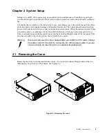
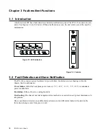
3.3 Visible and Audible Alarms
The IPC-616 provides quick fault identification with nine front panel LED indicators displaying the
system's status as follows:
Power failure: If either the backplane power source (+5 V, +12 V, +3.3 V, -5 V, -12 V) or redundant
power module fails, the "PWR" LED changes from green to red. You should immediately replace the
malfunctioning power module with a good one.
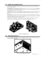
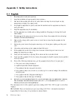
Fan failure: If either of the two cooling fans fails, an alarm LED changes color from green to red. You
should immediately replace the malfunctioning cooling fan module with a good one (see Figure 3-3
below).
Overheating: If the chassis' interior temperature reaches the user's preset maximum safe temperature
(which will be either 50°, 55°, 65°, or 70° C), an alarm LED changes color from green to red. The LED
remains red until the temperature returns below 50° C.
A speaker is activated at the start of a malfunction, and it will sound until the alarm reset button is
pressed. However, the LED indicator will stay red until the fault condition is resolved.
Figure 3-3: Cooling fan module
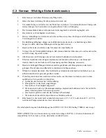
3.4 Overheating Sensor
There is a small PC board called "Over Temp" installed on the left interior of the chassis. It monitors
the chassis' internal temperature.
Figure 3-4: Overheating sensor on chassis


