background image

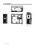
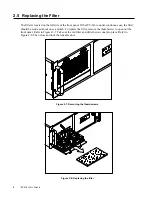
IPC-616  User's Manual

15

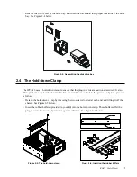
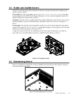
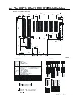
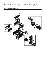
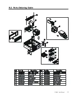
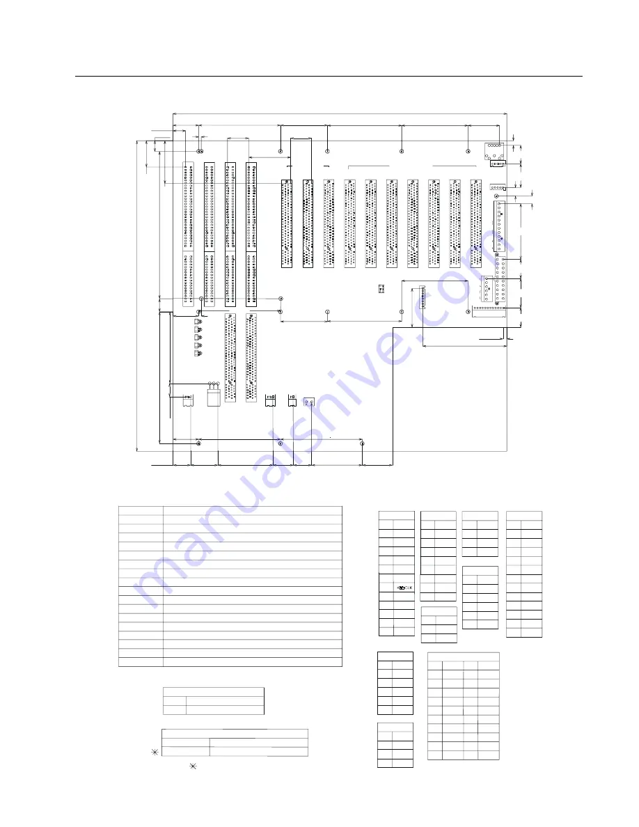
A.4 PCA-6114P10: 3 ISA / 10 PCI / 1 PICMG-slot Backplane

Dimensions: 300 x 323 mm

Unit: mm

CN1

LED2

LED1

LED3

LED4

LED5

JP2

ATX

P3

J1

J2

+5

V

-5V

GN

D

-12

+12

+5V

NC

P8/P9

J3

CN2

J4

P5

P4

D1
8

C1
8

C1

A3

1

D1

B3

1

B1

A1

SL

T4

D1
8

C1
8

C1

A3

1

D1

B3

1

B1

A1

SL

T3

D1
8

C1
8

C1

A3

1

D1

B3

1

B1

A1

SL

T2

D1
8

C1
8

C1

A3

1

D1

B3

1

B1

A1

SL

T1

PC
I2

PC
I1

PC
I3

PC
I4

PC
I5

PC
I6

PC
I7

PC
IC

PU

1

PC
IC

PU

2

PC
I9

PC
I1

0

PC
I8

JP1

+3

.3

V

GN

D

P11

12

1

6

1

+3.3V

+5V

6

5

2

V_SIO

SECONDARY PCI

PRIMARY PCI

-12V

-5V

+12V

+5V

3V3

1

3 2 1

2 1

3

1

1

3

+1
2V

+5
V

GN
D

+1

2V

GN

D

+5

V

2

1

GN

D

+5

V

KB

-O

UT

KB-IN

8

5

1

12

1

5

1

1

20

11

10

1

PCI 4 ~ 10

2

2

+5V

5

GND

+5V

11

+5V

12

6

GND

GND

-5V

+5V

GND

9

10

8

7

+12V
-12V

GND
GND

4
5
6

3

3
4

2

1

GND

+3.3V

P11 

3

NAME

NC

P8/P9
PIN

1

P4 ~ P5

NAME

PIN

1

2

2

PS-ON

NAME

8

7

HDD

4
5
6

3

+5V

GND

SP

2

PIN

J4

1

NAME

CN2
PIN

1

NAME

PIN

P3

1

P8 / P9

P11

6 - PIN +3.3V DC power connectors

TO PS / 2 power connector

P3

GND

CN1

7

10
11

8
9

2

6

5

3
4

PIN

1

-5V

+3.3V

HDD

GND

RESET

+5V

KBDDATA

+12V
-12V

NAME

SP

12

KBDLOCK

NAME

GND

+3.3V

5

10

9

8

6
7

3
4

2

1

PIN

ATX

15

20

18
19

17

16

+3.3V

GND

NAME

13
14

11

12

-12V

PIN

PS-ON

NC

5V STB

+12V

GND

+5V

+3.3V

GND
GND
GND

-5V

+5V
+5V

GND

+5V

JP1

JP2

3

5V STB

12 Pin power ( + / -5V , + / -12V ),SP,HDD,K/B,reset and  PF Connector

ATX power supply power OFF

ATX power supply power ON

3-5,4-6 CLOSED

1-3,2-4 CLOSED

To CPU CARD fot ATX power connector

3 - PIN +5V and +12v DC power connector

2 - PIN +5V DC power connector

Power ON control fot ATX power supply

External K/B connector

To CPU  CARD K/B connector

To front part K/B connector

V - IO for secondary PCI Bus

8 Pin power ( + / - 5V , + / - 12V ) , SP , HDD and  PF Connector

To ATX power connector

16 BIT ISA BUS connectors

PCIMG connectors

32 BIT PCI BUS connectors ( primary )
32 BIT PCI BUS connectors ( secondary )

Default : 

closed
open

P4 ~ 5

J2 ( K/B - IN )

J1( KB - OUT ) 

SLT3 ~ 4

SLT1 ~ 2

CONNECTOR

1 .  CONNECTORS

ATX

CN2

CN1

PCI 1 ~ 3

J4

JP2

JP1

J3

Description

V_IO = +5V for sceondary PCI Bus

V_IO = +3.3V for sceondary PCI Bus

CLK

+ 5V

GND

NC

DATA

4
5

2
3

1

J1~ J3

2 .  PIN  ASSIGNMENTS

PIN

GND

NC

RESET

GND

KBDLOCK

+12V

+3.3V

+3.3V

GND

+5V

48.90

26.28

17.02

53.22

17.78

19.69

29

9.

72

69

.2

2

12

.7

0

12

7.

14

24.77

12

.7

14

2.

24

24.77

41

.2

8

12.06

10.16

25

.4

24.77

78.99

2.54

78.99

79.12

45.47

40.64

20.32

2.54

78.99

45.47

20.32

29.08

+5V

81.28

71.76

64.14

37

.4

7

71.76

322.58

64.14

3.56

18.57

18.67

28.32

53.70

7.36

30.35

17.91

8.26

22.86

4.

32

NAME

Summary of Contents for IPC-616

Page 1: ...IPC 616 14 slot Fault resilient IPC Chassis User s Manual...

Page 2: ...manual is intended to be accurate and reliable However Advantech Co Ltd assumes no respon sibility for its use nor for any infringements of the rights of third parties which may result from its use Ac...

Page 3: ...ons 10 3 1 Introduction 10 3 2 Fault Detection and Alarm Notification 10 3 3 Visible and Audible Alarms 11 3 4 Overheating Sensor 11 Appendix A Passive Backplanes 12 A 1 PCA 6114P4 B 9 ISA 4 PCI 1 PIC...

Page 4: ...lockable door protects drives and switches from tampering and foreign parti cles 1 2 Specifications General Construction Heavy duty steel Disk drive capacity Three half height and one 3 5 front access...

Page 5: ...directly to the DC supply system earthing electrode conductor or to a bonding jumper from an earthing terminal bar or bus to which the DC supply system earthing electrode conductor is connected 2 The...

Page 6: ...fications Operating temperature 0 40 C 32 104 F Relative humidity 10 95 40 C non condensing Vibration operating 5 500 Hz 1 G rms for random vibration Shock operating 10 G acceleration peak 11 msec dur...

Page 7: ...4 IPC 616 User s Manual 1 3 Dimensions Unit mm inches...

Page 8: ...n the system detects a failure concerning power overheating or fans these LED indicators will change color from green to red There is a ground point earthing point located on the bottom right hand cor...

Page 9: ...r the front panel can be removed as follows Figure 2 2 Removing the handles 2 3 Adding Your Disk Drives 1 After removing the cover you will see four screws near the drive bay Remove these screws Lift...

Page 10: ...curely It also offers protection against shock and vibration To install your cards into the passive backplane proceed as follows 1 Detach the hold down clamp by removing the two screws located at each...

Page 11: ...inuous use the filter should be removed about once a month To replace the filter remove the thumbscrew to open out the front panel Refer to Figures 2 7 Take out the old filter and slide the new one in...

Page 12: ...e backplane bracket has 29 attaching holes see Figure 2 9 Any of six backplanes or the Intel L440GX motherboard may be attached to backplane bracket A table on the bracket shows which holes should be...

Page 13: ...ors system hardware for power failure fan failure and overheating within the chassis Fault conditions are Power failure Either the backplane power source 5 V 12 V 3 3 V 5 V 12 V or redundant power mod...

Page 14: ...the malfunctioning cooling fan module with a good one see Figure 3 3 below Overheating If the chassis interior temperature reaches the user s preset maximum safe temperature which will be either 50 55...

Page 15: ...12 IPC 616 User s Manual Appendix A Passive Backplanes A 1 PCA 6114P4 B 9 ISA 4 PCI 1 PICMG slot Backplane Dimensions 260 x 315 mm Unit mm...

Page 16: ...IPC 616 User s Manual 13 A 2 PCA 6113P4R 8 ISA 4 PCI 1 PICMG slot Backplane Dimensions 260 x 315 mm Unit mm...

Page 17: ...14 IPC 616 User s Manual A 3 PCA 6114P7 6 ISA 7 PCI 1 PICMG slot Backplane Dimensions 300 x 323 mm Unit mm...

Page 18: ...GND NAME 13 14 11 12 12V PIN PS ON NC 5V STB 12V GND 5V 3 3V GND GND GND 5V 5V 5V GND 5V JP1 JP2 3 5V STB 12 Pin power 5V 12V SP HDD K B reset and PF Connector ATX power supply power OFF ATX power su...

Page 19: ...16 IPC 616 User s Manual Appendix B Exploded Diagram and Parts Ordering Guide B 1 Exploded Diagram...

Page 20: ...IPC 616 User s Manual 17 B 2 Parts Ordering Guide...

Page 21: ...he equipment is not used for a long time disconnect it from the power source to avoid damage by transient over voltage 12 Never pour any liquid into an opening This could cause fire or electrical shoc...

Page 22: ...netz trennen Somit wird im Falle einer berspannung eine Besch digung vermieden 12 Durch die L ftungs ffnungen d rfen niemals Gegenst nde oder Fl ssigkeiten in das Ger t gelangen Dies k nnte einen Bran...

Reviews: