
2
IPC-616 User's Manual
Power supplies
PS-300ATX
• Output rating: 300 watts (max.)
• Input voltage: 90 ~ 130 V
AC
or 180 ~ 265 V
AC
@ 47 ~ 63 Hz, switchable
• Output voltages:
+5 V @ 30 A, +12 V @ 13 A, -5 V @ 0.5 A, -12 V @ 0.8 A, +3.3 V @ 26 A, +5 VSB @ 2 A
• Minimum load: +5 V @ 1 A, +12 V @ 0.2 A
• MTBF: 100,000 hours @ 25° C, full load
• Safety: UL, CSA, CE, NOROIC CENELEC, CB approved
• EMI: FCC, VDE, CISPR 22
PS-310-DC48
• Output rating: 310 watts (max.)
• Input voltage: -38 ~ -58 V
DC
• Output voltages: +5 V @ 25 A, +12 V @ 10 A, -5 V @ 1 A, -12 V @ 5 A
• Minimum load: +5 V @ 3 A, +12 V @ 1 A
• MTBF: 100,000 hours @ 25° C
• Safety: UL approved
• EMI: CE compliant
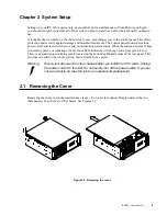
Installation notes
The IPC-616 is designed to permit the connection of the earthed conductor of the DC supply circuit to
the earthing conductor of the IPC-616's chassis.
If this connection is made, make sure that:
1. The IPC-616 is connected directly to the DC supply system earthing electrode conductor, or to a
bonding jumper from an earthing terminal bar or bus to which the DC supply system earthing
electrode conductor is connected.
2. The IPC-616 is located not only in the same immediate area (such as adjacent cabinets) as any other
equipment that has a connection between the earthed conductor of the same DC supply circuit.and
the earthing conductor, but also in the same immediate area as the point of earthing of the DC
system. The DC system must not be earthed elsewhere.
3. The DC supply source is located within the same premises as the IPC-616.
4. No switching or disconnecting device is installed in the earthed circuit conductor between the DC
source and the point of connection of the earthing electrode conductor.
Warning:
Due to the high wattage of the IPC-616, users must not remove the top cover of
the chassis. If users need to install or remove any device in the IPC-616, they
should consult qualified technical personnel.


