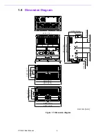


15
IPC-622 User Manual
Chapter 3
O
peration
3.1.3
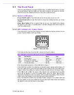
LED Indicators for Power Status
The LEDs that indicate the status of the backplane voltage signals are explained in
the table below.
When an LED fails to activate, this indicates a problem with one of the voltage sig-
nals. Check that the power supply connector is correctly attached to the backplane. If
the problem persists, consult an experienced technician.
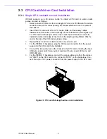
3.2
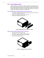
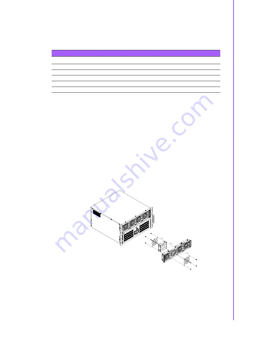
Cooling Fan Replacement
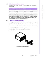
Four cooling fans are located in the front top of the chassis. They provide the system
with ample cooling by blowing air rearwards. To replace a cooling fan, please refer to
Figure 3.2 and follow the steps outlined below.
1.
Remove the front top chassis cover.
2.
Loosen and remove the thumb screw on the top of the fan unit. This will discon-
nect the cooling fan power connector.
3.
Replace the cooling fan with a new cooling fan.
4.
Attach the new cooling fan by fastening the thumb screw.
5.
Replace and fasten the front top chassis cover.
Figure 3.2 Cooling fan replacement
Table 3.2: LED Indicators for Power Status
LED
Description
LED on
LED off
+5 V
+5 V signal
Normal
Abnormal
+12 V
+12 V signal
Normal
Abnormal
-5 V
-5 V signal
Normal
Abnormal
-12 V
-12 V signal
Normal
Abnormal
+3.3 V
+3.3 V signal
Normal
Abnormal
Summary of Contents for IPC-622 Series
Page 1: ...User Manual IPC 622 Series 6U Multi Segment Rackmount Industrial Computer Chassis...
Page 27: ...19 IPC 622 User Manual Chapter 3 Operation Figure 3 8 Replacing the redundant power supply...
Page 28: ...IPC 622 User Manual 20...
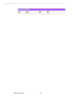
Page 36: ...IPC 622 User Manual 28 Table 4 22 PWR1 Pin 1 V12 Pin 4 GND Pin 2 GND Pin 5 V5...
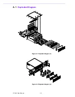
Page 37: ...Appendix A A Exploded Diagram...
Page 39: ...Appendix B B Backplane Options...
Page 41: ...33 IPC 622 User Manual Appendix B Backplane Options...