17
IPC-622 User Manual
Chapter 3
O
peration
3.4
Power Supply Replacement
The IPC-622 supports either a PS/2 power supply or redundant power supply. To
replace the power supply, follow the instructions below.
3.4.1
Redundant Power Supply Module
The redundant power supply module is rear-accessible and hot-swappable. To
change the module, follow the instructions below.
1.
Press the Alarm Reset button on the front panel to stop the alarm.
2.
Unplug the power cord on the failed power supply module.
3.
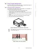
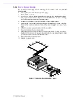
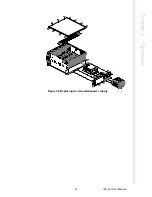
Loosen the screws on the module. Grab the handle and gently pull the module
out (see Figure 3.5).
4.
Ensure that the new power supply module has the same rating as the previous
module.
5.
Slide the power supply module into the system (it should lock into place).
6.
Fasten the screws and then plug in the power cord.
Figure 3.5 Replacing the redundant power supply module
Figure 3.6 Power cord socket orientation
Note
When plugging two or more power cords into a socket, adopt the same
orientation (see Figure 3.6).
Summary of Contents for IPC-622 Series
Page 1: ...User Manual IPC 622 Series 6U Multi Segment Rackmount Industrial Computer Chassis...
Page 27: ...19 IPC 622 User Manual Chapter 3 Operation Figure 3 8 Replacing the redundant power supply...
Page 28: ...IPC 622 User Manual 20...
Page 36: ...IPC 622 User Manual 28 Table 4 22 PWR1 Pin 1 V12 Pin 4 GND Pin 2 GND Pin 5 V5...
Page 37: ...Appendix A A Exploded Diagram...
Page 39: ...Appendix B B Backplane Options...
Page 41: ...33 IPC 622 User Manual Appendix B Backplane Options...

