


IPC-622 User Manual
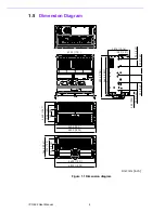
18
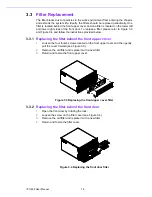
3.4.2
Power Supply Module
For the PS/2 power supply module, following the instructions below to replace the
power supply.
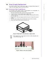
1.
Unplug the power cord from the power supply.
2.
Remove the top cover.
3.
Unplug the 12-pin AT power connector (or 20-pin (24-pin) ATX power connec-
tor), 6-pin +3.3V, and 6-pin +5V power connectors from the backplane. Unplug
all other power connectors from the disk drives.
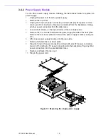
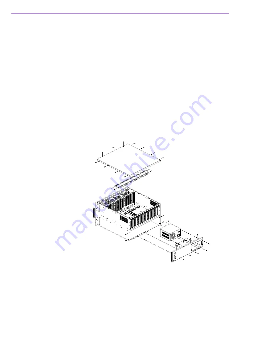
4.
Loosen the 8 screws on the top and sides of the rear lower plate.
5.
Remove the four screws that fasten the power supply module to the rear plate.
Remove the rear lower plate and retrieve the power supply module (see Figure
3.7).
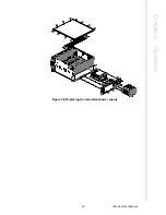
6.
Affix a new power supply module onto the rear plate.
7.
Return and fasten the rear lower plate.
8.
Plug the 12-pin AT power connector (or 20-pin (24-pin) ATX power connector),
6-pin +3.3V, and 6-pin +5V power connectors into the backplane. Plug any other
power connectors into the essential disk drives.
9.
Replace and fasten the top cover.
10.
Plug in the power cord.
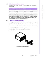
Figure 3.7 Replacing the single power supply
Summary of Contents for IPC-622 Series
Page 1: ...User Manual IPC 622 Series 6U Multi Segment Rackmount Industrial Computer Chassis...
Page 27: ...19 IPC 622 User Manual Chapter 3 Operation Figure 3 8 Replacing the redundant power supply...
Page 28: ...IPC 622 User Manual 20...
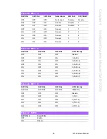
Page 36: ...IPC 622 User Manual 28 Table 4 22 PWR1 Pin 1 V12 Pin 4 GND Pin 2 GND Pin 5 V5...
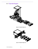
Page 37: ...Appendix A A Exploded Diagram...
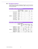
Page 39: ...Appendix B B Backplane Options...
Page 41: ...33 IPC 622 User Manual Appendix B Backplane Options...


