


IPC-622 User Manual
22
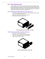
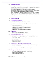
4.1
Getting Started
Configuring SAB-2000
SAB-2000 is pre-installed in the system chassis. The hardware switch should be
adjusted according to the system layout.
Please refer to the user manual for the location of the hardware switch.
For different system layouts, SAB-2000 can be configured using the H/W switch.
Please refer to the “Switch Settings” section for detailed information.
For remote management functionality, SUSIAccess must be installed. This enables
users to monitor the system fan speed, system temperature, CPU temperature, and
voltage. Under SUSIAccess, users can also set their own alarm standards according
to their requirements. For detailed information, please refer to the SUSIAccess user
guide.
4.2
Specifications
4.2.1
Hardware Specifications
One 10-pin hardware switch for alarm configuration
One SMbus interface for monitoring the system and main board status
Up to four external temperature sensors
Seven fan tachometer inputs
One external IPMI module connector
One built-in buzzer for system health status notifications
Automatic smart fan control
Reserved PCB layout for gravity and humidity sensors
4.2.2
Dimensions
Kernel module (9692S20000E): 115 x 55 mm
4.2.3
Sensor Input Specifications
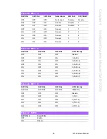
Voltage inputs: +5 VDC, -5 VDC, 5 VSB, +3.3 VDC, +12 VDC, -12 VDC
Temperature sensors: LM75 digital temperature sensor, I2C interface, -30 ~
+125 °C (-22 ~ 257 °F)
Fan speed monitor: Up to seven fans, 0 ~ 20000 RPM
Power monitoring:
Detect redundant power
IPMI and SUSI command
4.2.4
System Status Monitoring and Management
Real-time health status monitoring: Real-time system/main board FAN speed
and temperature monitor
Remote system monitoring through SUSIAccess
Alarm management via on-board buzzer and LED signals
4.2.5
Management Functions
Web-based remote configuration, control, and monitoring
Remote reset and power on/off
Remote digital output signal control
Summary of Contents for IPC-622 Series
Page 1: ...User Manual IPC 622 Series 6U Multi Segment Rackmount Industrial Computer Chassis...
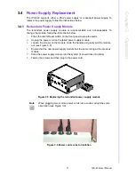
Page 27: ...19 IPC 622 User Manual Chapter 3 Operation Figure 3 8 Replacing the redundant power supply...
Page 28: ...IPC 622 User Manual 20...
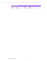
Page 36: ...IPC 622 User Manual 28 Table 4 22 PWR1 Pin 1 V12 Pin 4 GND Pin 2 GND Pin 5 V5...
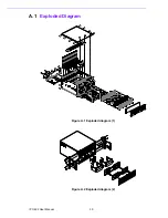
Page 37: ...Appendix A A Exploded Diagram...
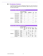
Page 39: ...Appendix B B Backplane Options...
Page 41: ...33 IPC 622 User Manual Appendix B Backplane Options...