


IPC-622 User Manual
24
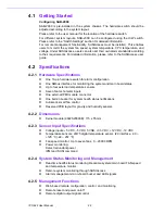
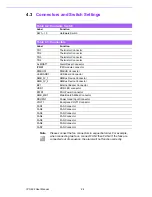
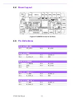
4.3
Connectors and Switch Settings
Table 4.2: Hardware Switch
Label
Function
SW1 ~ 10
Hardware Switch
Table 4.3: Connectors
Label
Function
TR1
Thermistor Connector
TR2
Thermistor Connector
TR3
Thermistor Connector
TR4
Thermistor Connector
ALMRST1
Alarm Reset Connector
IPMB1
IPMI module connector
PMBUS1
PMBUS Connector
LEBOARD1
LED Board Connector
SMB_3V_1
SMBus Device Connector
SMB_3V_2
SMBus Device Connector
BZ1
External Buzzer Connector
HDD1
HDD LED connector
PWR1
PSU Power Connector
SMB_MB1
Main Board SMBus Connector
RDUPG1
Power Good Input Connector
VOLT1
Backplane VOLT1 Connector
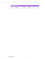
FAN1
FAN Connector
FAN2
FAN Connector
FAN3
FAN Connector
FAN4
FAN Connector
FAN5
FAN Connector
FAN6
FAN Connector
FAN7
FAN Connector
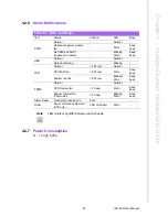
Note
Please connect the fan connectors in sequential order. For example,
when connecting two fans, connect FAN1 then FAN2. If the fans are
connected out of sequence, the alarm will not function correctly.
Summary of Contents for IPC-622 Series
Page 1: ...User Manual IPC 622 Series 6U Multi Segment Rackmount Industrial Computer Chassis...
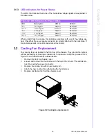
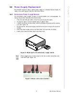
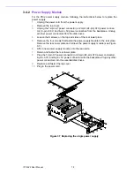
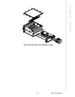
Page 27: ...19 IPC 622 User Manual Chapter 3 Operation Figure 3 8 Replacing the redundant power supply...
Page 28: ...IPC 622 User Manual 20...
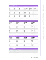
Page 36: ...IPC 622 User Manual 28 Table 4 22 PWR1 Pin 1 V12 Pin 4 GND Pin 2 GND Pin 5 V5...
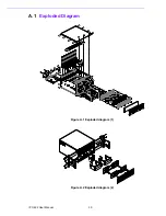
Page 37: ...Appendix A A Exploded Diagram...
Page 39: ...Appendix B B Backplane Options...
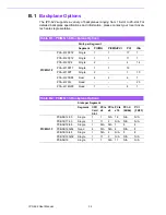
Page 41: ...33 IPC 622 User Manual Appendix B Backplane Options...