IPC-644 User Manual
8
Chapter 2 System Setup
The following procedures are provided to assist you in installing a pas-
sive backplane, add-on cards, and disk drives into the IPC-644. Please
refer to Appendix A, Exploded Diagram, for details of all the parts of the
IPC-644.
2.1 Removing the Chassis Cover
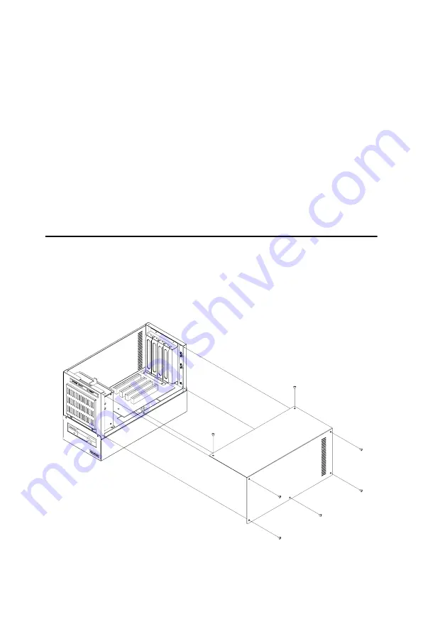
To remove the cover of IPC-644, please refer to Figure 2.1 and proceed as
follows.
1.
Loosen the seven screws on the top and the right of the chassis.
2.
Remove the chassis cover gently.
Figure 2.1: Removing the chassis cover
Note
Use caution when installing or operating the compo-
nents with the chassis open. Be sure to turn off the
power, unplug the power cord and ground yourself by
touching the metal chassis before you handle any
components inside the machine.
Summary of Contents for IPC-644 Series
Page 1: ...IPC 644 Micro Box 4 slot Industrial Chassis User Manual...
Page 6: ...IPC 644 User Manual vi...
Page 9: ...2 CHAPTER 1 General Information...
Page 12: ...IPC 644 User Manual 4 1 5 Dimensions Figure 1 1 Dimensions of IPC 644...
Page 14: ...IPC 644 User Manual 6...
Page 15: ...2 CHAPTER 2 System Setup...
Page 22: ...IPC 644 User Manual 14...
Page 23: ...2 CHAPTER 3 Operation...
Page 25: ...17 Chapter3 Figure 3 1 Replacing the fan...
Page 28: ...IPC 644 User Manual 20...
Page 29: ...2 APPENDIX A Exploded Diagram...
Page 30: ...IPC 644 User Manual 22 Appendix A Exploded Diagram Figure A 1 Exploded diagram...
Page 31: ...2 APPENDIX B Backplane Options...


