IPC-644 User Manual
12
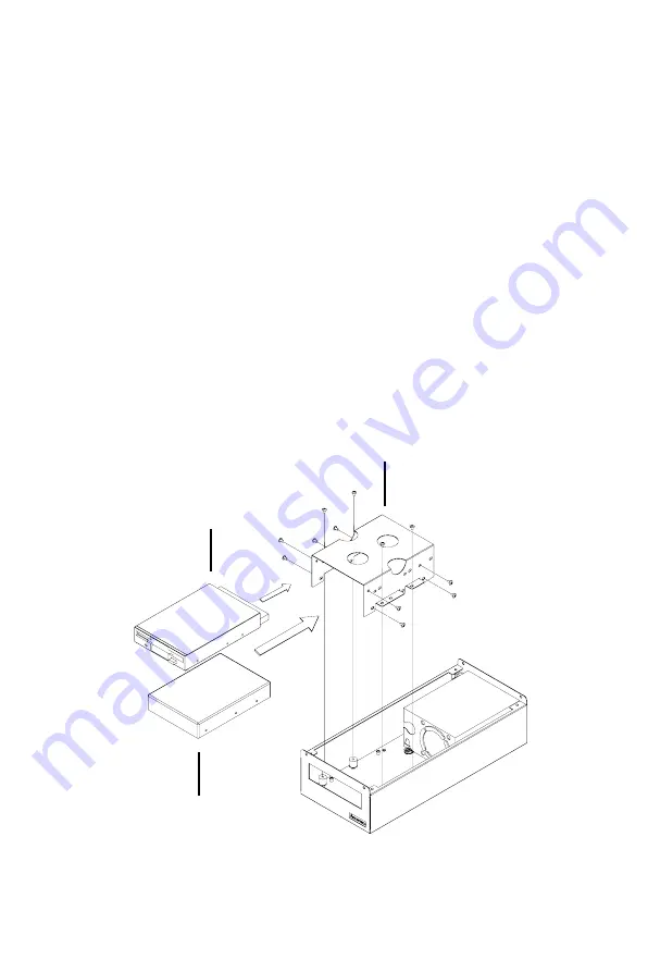
2.4.2 Installing a HDD or FDD
1.
Loosen the five screws (one screw is for grounding) on the disk
drive mounting bracket and then lift it out.
2.
Insert the disk drive into its proper location in the disk drive mount-
ing bracket, and then fix it in place with the supplied screws (see
Figure 2.5).
3.
Connect a 34-pin flat cable from the CPU card to an FDD, or a 40-
pin flat cable from the CPU card to an IDE HDD. Plug in the power
connector into each disk drive.
4.
Return the disk drive mounting bracket back to its original location
and fasten it with the five screws.
5.
Return the upper cage and secure it with the four screws.
6.
Plug the 20-pin ATX power supply connector into the backplane.
Figure 2.5: Installing disk drives into the housing
Disk drive mounting bracket
Floppy disk drive
Hard disk drive
Summary of Contents for IPC-644 Series
Page 1: ...IPC 644 Micro Box 4 slot Industrial Chassis User Manual...
Page 6: ...IPC 644 User Manual vi...
Page 9: ...2 CHAPTER 1 General Information...
Page 12: ...IPC 644 User Manual 4 1 5 Dimensions Figure 1 1 Dimensions of IPC 644...
Page 14: ...IPC 644 User Manual 6...
Page 15: ...2 CHAPTER 2 System Setup...
Page 22: ...IPC 644 User Manual 14...
Page 23: ...2 CHAPTER 3 Operation...
Page 25: ...17 Chapter3 Figure 3 1 Replacing the fan...
Page 28: ...IPC 644 User Manual 20...
Page 29: ...2 APPENDIX A Exploded Diagram...
Page 30: ...IPC 644 User Manual 22 Appendix A Exploded Diagram Figure A 1 Exploded diagram...
Page 31: ...2 APPENDIX B Backplane Options...


