19
Chapter 3
3.4 Replacing the power supply
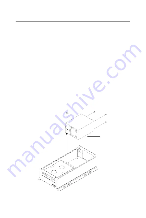
To replace the power supply, refer to Figure 3.3 and proceed as follows.
1.
Unplug the AC power cord from the power supply.
2.
Remove the chassis cover.
3.
Unplug the 20-pin ATX power connector from the backplane.
4.
Remove the upper cage (refer to section 2.4.1).
5.
Unplug the power connectors from all disk drives.
6.
Remove the three screws on the chassis rear plate and the nut,
which fixes the power supply in the chassis, then take out the
power supply.
7.
Place a new power supply into the chassis and fasten it with the
screws and the nut.
8.
Return the upper cage and fasten it.
9.
Plug the 20-pin ATX power connector into the backplane and plug
other power connectors into the disk drives and peripherals.
10.
Return the chassis top cover and plug in the power cord.
Figure 3.3: Replacing the power supply
Nut
Power supply
Summary of Contents for IPC-644 Series
Page 1: ...IPC 644 Micro Box 4 slot Industrial Chassis User Manual...
Page 6: ...IPC 644 User Manual vi...
Page 9: ...2 CHAPTER 1 General Information...
Page 12: ...IPC 644 User Manual 4 1 5 Dimensions Figure 1 1 Dimensions of IPC 644...
Page 14: ...IPC 644 User Manual 6...
Page 15: ...2 CHAPTER 2 System Setup...
Page 22: ...IPC 644 User Manual 14...
Page 23: ...2 CHAPTER 3 Operation...
Page 25: ...17 Chapter3 Figure 3 1 Replacing the fan...
Page 28: ...IPC 644 User Manual 20...
Page 29: ...2 APPENDIX A Exploded Diagram...
Page 30: ...IPC 644 User Manual 22 Appendix A Exploded Diagram Figure A 1 Exploded diagram...
Page 31: ...2 APPENDIX B Backplane Options...


