11
Chapter 2
1.
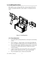
Referring to Figure 2-2, carefully place the passive backplane and
EMI spring plate in the IPC-6806S chassis and fix it with screws.
For the bare IPC-6806S chassis, the EMI spring plate is stored in
the accessory box.
2.
Before installing the CPU card, check all devices, such as CPU,
CPU cooler, and RAM modules, then make sure they have been
installed on the CPU card correctly.
3.
Carefully insert the CPU card in to the master slot of the backplane.
Make sure that the card bracket has been inserted properly and the
other edge of the card has been fixed in the guiding rail. Fasten the
card at the top of the bracket with a screw.
4.
Plug the 20-pin ATX power connector from the power supply into
the backplane. Connect the POWER SW connector to the PS-ON
connector (CN1) on the backplane.
5.
Connect the RESET SW, POWER LED, and HDD LED cables to
the CPU card. Connect the USB cable from the front panel to the
CPU card, if the CPU card supports the front USB feature.
Summary of Contents for IPC-6806S
Page 1: ...IPC 6806S Wallmount IPC Chassis for 6 Half sized Cards User Manual...
Page 10: ...IPC 6806S User Manual iv B 2 2 Connectors 28 B 2 3 Connector Pin Definition 28...
Page 11: ...2 CHAPTER 1 General Information...
Page 14: ...IPC 6806S User Manual 4 1 6 Dimensions of IPC 6806S Figure 1 1 Dimensions of IPC 6806S...
Page 15: ...5 Chapter1 Figure 1 2 Details of wallmount brackets...
Page 16: ...IPC 6806S User Manual 6...
Page 17: ...2 CHAPTER 2 System Setup...
Page 26: ...IPC 6806S User Manual 16...
Page 27: ...2 CHAPTER 3 Operation...
Page 31: ...2 APPENDIX A Exploded Diagram...
Page 32: ...IPC 6806S User Manual 22 Appendix A Exploded Diagram Figure A 1 Exploded Diagram...
Page 33: ...2 APPENDIX B Passive Backplanes...
Page 37: ...27 AppendixB B 2 PCA 6105P5 0B1 5 slot PCI backplane B 2 1 Dimension Drawing Size 143 x 176 mm...
Page 40: ...IPC 6806S User Manual 30 BIG1 Connector Pin Signal 1 12V 2 GND 3 GND 4 5V...


