13
Chapter 2
2.3.2 Floppy disk drive
1.
Remove the blanking covers of the 3.5" drive bay.
2.
Referring to Figure 2-3, insert a FDD into the drive bay with the
base facing inward. Fix the drive with screws.
3.
Connect 34-pin flat cable from the CPU card to the FDD.
4.
Plug a floppy drive power connector into the FDD.
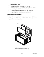
2.4 Installing add-in cards
IPC-6806S can accept up to six half-sized cards (including a CPU card)
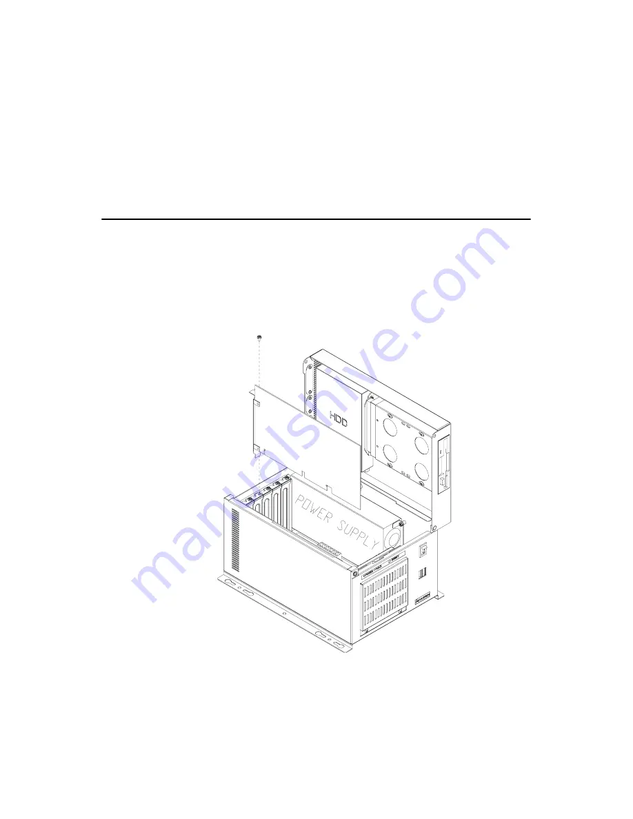
via the supported passive backplane. To install an add-in card, refer to
Figure 2-4 and proceed as follows:
Figure 2.4: Installing an add-in card
Summary of Contents for IPC-6806S
Page 1: ...IPC 6806S Wallmount IPC Chassis for 6 Half sized Cards User Manual...
Page 10: ...IPC 6806S User Manual iv B 2 2 Connectors 28 B 2 3 Connector Pin Definition 28...
Page 11: ...2 CHAPTER 1 General Information...
Page 14: ...IPC 6806S User Manual 4 1 6 Dimensions of IPC 6806S Figure 1 1 Dimensions of IPC 6806S...
Page 15: ...5 Chapter1 Figure 1 2 Details of wallmount brackets...
Page 16: ...IPC 6806S User Manual 6...
Page 17: ...2 CHAPTER 2 System Setup...
Page 26: ...IPC 6806S User Manual 16...
Page 27: ...2 CHAPTER 3 Operation...
Page 31: ...2 APPENDIX A Exploded Diagram...
Page 32: ...IPC 6806S User Manual 22 Appendix A Exploded Diagram Figure A 1 Exploded Diagram...
Page 33: ...2 APPENDIX B Passive Backplanes...
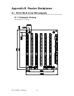
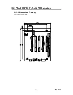
Page 37: ...27 AppendixB B 2 PCA 6105P5 0B1 5 slot PCI backplane B 2 1 Dimension Drawing Size 143 x 176 mm...
Page 40: ...IPC 6806S User Manual 30 BIG1 Connector Pin Signal 1 12V 2 GND 3 GND 4 5V...


