IPPC-4001 User Manual
6
Chapter 2 System Setup
2.1 System Installation
2.1.1 Attaching the Handles
The handles for the front panel are in the accessory box. To install the
handles, simply secure them to the front panel with the provided screws.
2.1.2 Removing the Top Cover
First, remove the chassis cover.
The top cover is fixed to the chassis by two thumbscrews
To remove the top covers:
1. Release two thumbscrews on the rear upper location of the chassis.
2. Lift the cover.
2.1.3 Chassis Front and Rear Sections
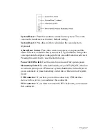
The front panel switches behind the door are used for system power, sys-
tem reset 1, system reset 2 (option), alarm reset and power switch. The
door cover is on the left side of the door cover, where the system LED sta-
tus and key lock switch are located. The key can be found in the accessory
box as shown below.
The USB and PS/2 keyboard connectors are on the left of the front panel.
WARNING:
Before starting the installation process, be sure
to shut down all power from the chassis. Do this
by turning off the power switch, and unplugging
the power cord from the power outlet. When in
doubt, consult with an experienced technician.
Summary of Contents for IPPC-4001 Series
Page 6: ...IPPC 4001 User Manual vi...
Page 7: ...1 Chapter1 CHAPTER 1 General Information...
Page 10: ...IPPC 4001 User Manual 4 1 3 Dimensions...
Page 11: ...5 Chapter2 CHAPTER 2 System Setup...
Page 17: ...11 Chapter3 CHAPTER 3 Alarm Board...
Page 23: ...17 Chapter3 3 3 Switch Setting Fan Number Setting Thermal Board Temperature Setting...
Page 24: ...IPPC 4001 User Manual 18...


