IPPC-4001 User Manual
8
2.1.4 Drive Bay Installation
The drive bay of IPPC-4001 can hold 5.25" (x3) devices.
Installation of disk drives:
1.
Remove the top cover
2.
Undo the two screws of cushion and four screws on the drive bay
3.
Lift off the Standard Drive Bay.
4.
Insert the drives into their proper locations in the drive bay and
secure them with the screws provided.
5.
Connect the disk drive power and signal cables.
2.2 LED Indicators
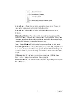
2.2.1 System Status LED
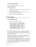
The System Status LED shows as follows:
When the PWR LED is RED, it indicates a redundant power supply fail-
ure. To stop the alarm buzzer, press the Alarm Reset button. Please check
out the redundant power supply right away and replace failure power sup-
ply module with a good one.
When the FAN LED is RED and blinking, it indicates a failing cooling fan.
An audible alarm is also activated. To stop the alarm buzzer, press the
Alarm Reset button then replace the fan immediately.
If the TEMP LED is RED and blinking, the system detects rising tempera-
ture inside the chassis. An audible alarm is activated. To stop the alarm
buzzer, press the Alarm Reset button. Inspect the rear section and fan fil-
ter immediately. Make sure airflow inside the chassis is smooth and not
blocked by dust or other particles.
Summary of Contents for IPPC-4001 Series
Page 6: ...IPPC 4001 User Manual vi...
Page 7: ...1 Chapter1 CHAPTER 1 General Information...
Page 10: ...IPPC 4001 User Manual 4 1 3 Dimensions...
Page 11: ...5 Chapter2 CHAPTER 2 System Setup...
Page 17: ...11 Chapter3 CHAPTER 3 Alarm Board...
Page 23: ...17 Chapter3 3 3 Switch Setting Fan Number Setting Thermal Board Temperature Setting...
Page 24: ...IPPC 4001 User Manual 18...


