9
MIC-3399 User Manual
C
ha
pte
r 1
H
ard
w
are
C
on
fig
ura
tio
n
1.4.1
Jumper Settings
1.4.1.1
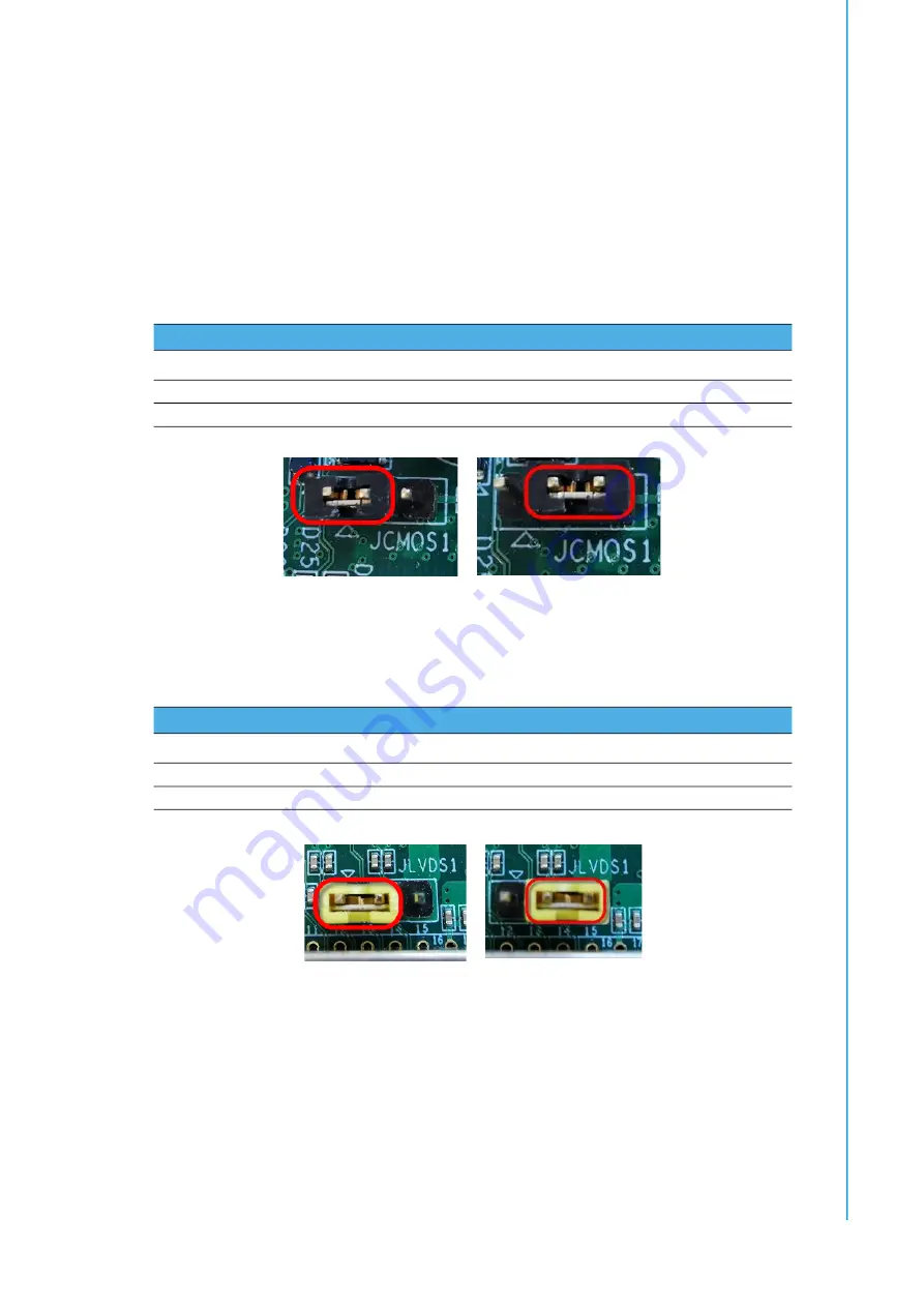
Clear CMOS (JCMOS1)
This jumper is used to erase CMOS data. Follow the procedures below to clear the
CMOS.
1.
Power off the system.
2.
Close JCMOS1 Pins 1 and 2 for about 3 seconds.
3.
Then close JCMOS1 Pins 2 and 3, as per the Normal setting.
4.
Power on the system. The BIOS will be restored to the default settings.
JCMOS1 Closed 1-2
JCMOS1 Closed 2-3
1.4.1.2
Rear LVDS Setting (JLVDS1)
This jumper is used to configure the LVDS power settings.
JLVDS1 Closed 1-2
JLVDS1 Closed 2-3
Table 1.6: JCMOS1 Clear RTC
Status
Function
Note
Closed 1-2
Clear RTC
Closed 2-3
Normal
[default]
Table 1.7: JLVDS1 Settings
Status
Function
Note
Closed 1-2
LVDS for 3.3V LVDS panel
[default]
Closed 2-3
LVDS for 5V LVDS panel
Summary of Contents for MIC-3399
Page 8: ...MIC 3399 User Manual viii...
Page 29: ...Chapter 2 2 AMI BIOS Setup This chapter describes how to configure the AMI BIOS...
Page 47: ...35 MIC 3399 User Manual Chapter 2 AMI BIOS Setup 2 3 3 8 Southbridge Figure 2 19 Southbridge...
Page 63: ...Chapter 3 3 IPMI Configuration This chapter describes IPMI con figuration for MIC 3399...
Page 85: ...Appendix A A Pin Assignments This appendix provides the pin assignments...
Page 94: ...MIC 3399 User Manual 82...
Page 97: ...Appendix C C FPGA Specifications This appendix describes FPGA configuration...
Page 99: ...87 MIC 3399 User Manual Appendix C FPGA Specifications...


