49
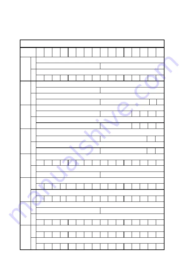
MIC-3756 Register Format (Continue)
Base Add
.
15
14
13
12
11
10
9
8
7
6
5
4
3
2
1
0
NA
R
Counter Mode Register
C
W
CM5 CM4 CM3 CM2 CM1 CM0
NA
R
Counter Reset Register
E
W
D1 D0
Board ID Register
R
ID3 ID2 ID1 ID0
N/A
10
W
Channel-Freeze Function Control Register
R
CFS CFC
Channel-Freeze Function Status Register
12
W
CFC
Counter Read Register
R
CR15 CR14 CR13 CR12 CR11 CR10 CR9 CR8 CR7 CR6 CR5 CR4 CR3 CR2 CR1 CR0
NA
14
W
INT State of Counter
R
INT
Clear INT of Counter
16
W
NA
R
Set Value Register
18
W
SE15 SE14 SE13 SE12 SE11 SE10 SE9 SE8 SE7 SE6 SE5 SE4 SE3 SE2 SE1 SE0
R
1E
W
Summary of Contents for MIC-3756
Page 2: ...ii This page is left blank for hard printing ...
Page 7: ...1 Introduction 1 CHAPTER ...
Page 8: ...2 This page is left blank for hard printing ...
Page 13: ...7 Hardware Configuration CHAPTER 2 ...
Page 14: ...8 This page is left blank for hard printing ...
Page 20: ...14 2 3 Board Layout Fig 2 1 MIC 3756 board layout ...
Page 22: ...16 This page is left blank for hard printing ...
Page 23: ...17 Pin Assignment and Jumper Setting CHAPTER 3 ...
Page 24: ...18 This page is left blank for hard printing ...
Page 26: ...20 Fig 3 1 I O Connector pin assignments for the MIC 3756 ...
Page 33: ...27 Operations CHAPTER 4 ...
Page 34: ...28 This page is left blank for hard printing ...
Page 49: ...43 Appendixes ...
Page 50: ...44 This page is left blank for hard printing ...
Page 56: ...50 Note Write 1 to the bit Fn in Interrupt Control Register clears the interrupt ...


