For details, please contact your Advantech representative to obtain further
support.
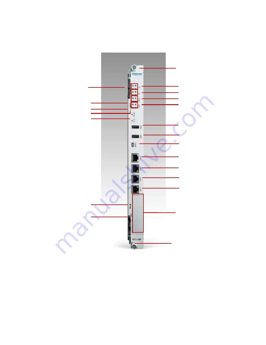
Figure 3.9 MIC-5332 Front Panel Configuration
3.4.6 LED Definition
This section describes how to identify the system operating status via LED signals
from the front panel. Before starting, please refer to table 3.2 to learn the LED signal
identification in this manual. In the following section, we take amber as an example:
Handle (Top side)
Retaining Thumbscrews
Retaining Thumbscrews
Handle (Bottom
side)
FI Channel 1/2 Status LEDs
BI Channel1/2 Status LEDs
SAS Status LEDs
Dual Color User LEDs
USB2
USB1
COM2 (miniUSB)
Hot Swap LED
Button1 (Reserved)
Button2 (Reserved)
OOS LED
Health LED
FMM Bay
COM1 (RJ45)
LAN3 (RJ45)
LAN2 (SFP or RJ45)
LAN1 (SFP or RJ45)
Summary of Contents for MIC-5332
Page 7: ...This page is left blank intentionally ...
Page 10: ...Chapter 1 Product Overview This chapter briefly describes the MIC 5332 ...
Page 15: ...Chapter 2 Board Features This chapter describes the MIC 5332 hardware features ...
Page 43: ...Figure 3 10 Jumper Locations JP1 JP5 JP6 ...
Page 44: ...Chapter 4 Hardware Management This chapter describes the IPMC firmware features ...
Page 105: ... root localhost ipmitool raw 0x2E 0x40 0x39 0x28 0x00 0x03 0x01 section ...
Page 108: ...Appendix A IPMI PICMG Command Subset Supported by IPMC ...
Page 120: ...33 48V_A 48V input feed A 34 48V_B 48V input feed B ...


