15
MIC-7900 User Manual
Chapter 2
H
/W Installation
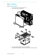
5.
Replace bottom cover.
2.4.2
Memory Installation
MIC-7900 supports DDR4 SO-DIMM ECC or Un-ECC type memory module. If you
needs detail memory support list, please connect your distributor or sales represent-
ative to order compatible memory modules.
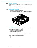
1.
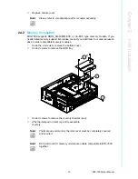
Undo the 4 screws to remove the bottom cover.
2.
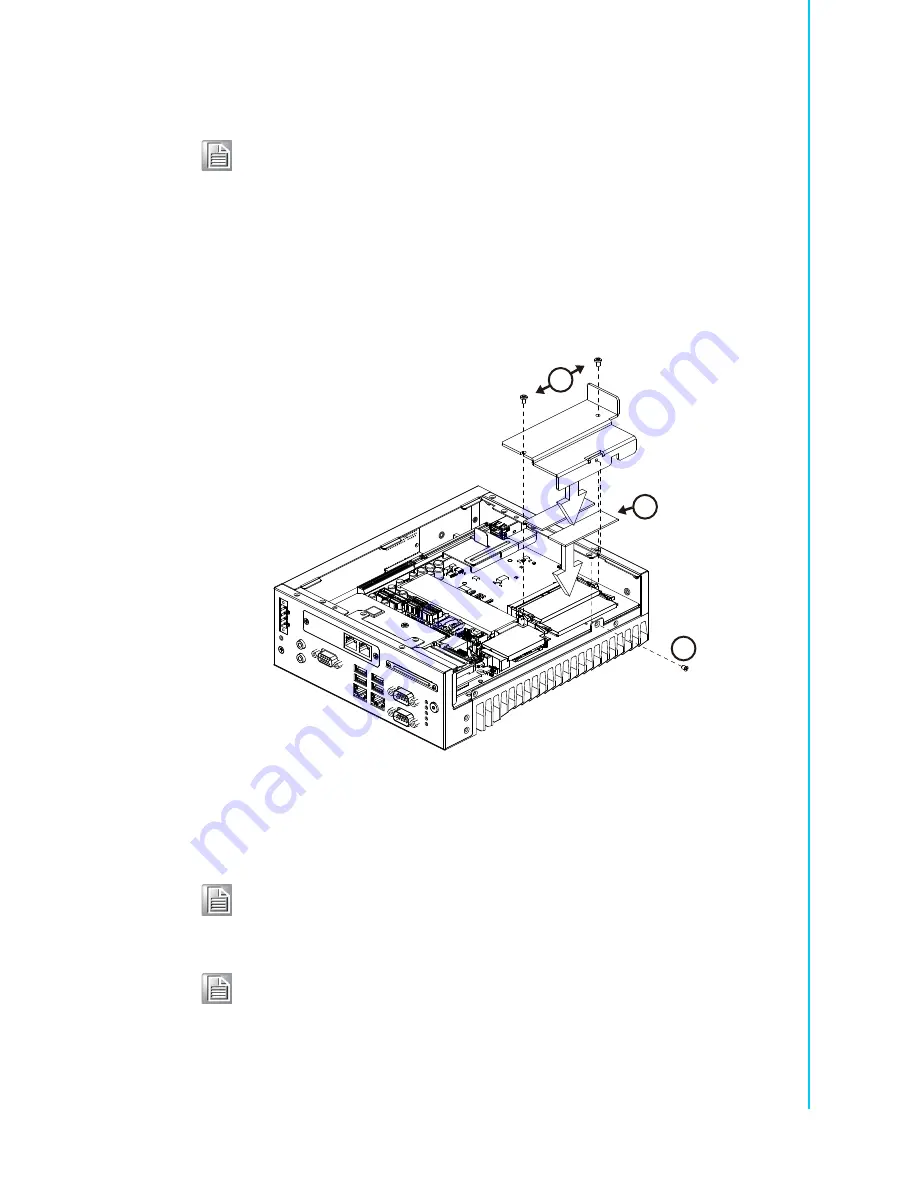
Undo 4 screws to remove the HDD tray.
3.
Undo 3 screws to remove the memory thermal cover.
4.
Affix thermal pad on memory, and reassemble
memory.
Note!
Please refer to i-module Manual for i-module assembly.
Note!
Thermal pad and memory thermal cover must be completely covered
and secured.
Note!
ECC and Un-ECC memory module are unable compatible in MIC-7900
together.
4
3
3
Summary of Contents for MIC-7900
Page 1: ...User Manual MIC 7900 Embedded Fan less IPC System 866 412 6278 CoastIPC com...
Page 11: ...Chapter 1 1 General Introduction This chapter gives background information on MIC 7900...
Page 16: ...MIC 7900 User Manual 6...
Page 28: ...MIC 7900 User Manual 18...
Page 29: ...Chapter 3 3 AMI BIOS Setup This chapter introduces how to set BIOS configuration data...
Page 77: ...Chapter 4 4 Software Installation This chapter introduces driver installation...
Page 82: ...MIC 7900 User Manual 72...
Page 83: ...Appendix A A Programming the Watchdog Timer...


