MIC-7900 User Manual
82
B.1
Supported GPIO Register
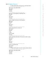
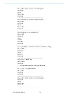
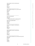
Below are detailed description of the GPIO addresses and programming sample.
B.1.1
GPIO Registers
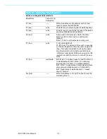
CRF0 (GP40-GP47 I/O selection register. Default 0xFF)
When set to '1', the respective GPIO port is programmed as an input port.
When set to '0', the respective GPIO port is programmed as an output port.
CRF1 (GP40-GP47 data register. Default 0x00)
If a port is programmed to be an output port, then its respective bit can be read/writ-
ten.
If a port is programmed to be an input port, then its respective bit can only be read.
CRF2 (GP40-GP47 inversion register. Default 0x00)
When set to '1', the incoming/outgoing port value is inverted.
When set to '0', the incoming/outgoing port value is the same as in data register.
Extended Function Index Registers (EFIRs)
The EFIRs are write-only registers with port address 2Eh or 4Eh on PC/AT systems.
Extended Function Data Registers (EFDRs)
The EFDRs are read/write registers with port address 2Fh or 4Fh on PC/AT systems
Summary of Contents for MIC-7900
Page 1: ...User Manual MIC 7900 Embedded Fan less IPC System 866 412 6278 CoastIPC com...
Page 11: ...Chapter 1 1 General Introduction This chapter gives background information on MIC 7900...
Page 16: ...MIC 7900 User Manual 6...
Page 28: ...MIC 7900 User Manual 18...
Page 29: ...Chapter 3 3 AMI BIOS Setup This chapter introduces how to set BIOS configuration data...
Page 77: ...Chapter 4 4 Software Installation This chapter introduces driver installation...
Page 82: ...MIC 7900 User Manual 72...
Page 83: ...Appendix A A Programming the Watchdog Timer...

