9
MIO-5270 User Manual
Chapter 2
H
ardware
Installation
2.1.3
Jumper Description
Cards can be configured by setting jumpers. A jumper is a metal bridge used to close
an electric circuit. It consists of two metal pins and a small metal clip (often protected
by a plastic cover) that slides over the pins to connect them. To close a jumper, you
connect the pins with the clip. To open a jumper, you remove the clip. Sometimes a
jumper will have three pins, labeled 1, 2 and 3. In this case you would connect either
pins 1 and 2, or 2 and 3.
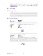
J3
LCD Power
Part Number
1653003201
Footprint
HD_3x2P_79_D
Description
PIN HEADER 3*2P 180D(M) 2.0mm DIP SQUARE WO/Pb
Setting
Function
(1-3)*
+3.3V
(3-5)
+5V
(3-4)
+12V
J5
COM2 Setting
Part Number
1653003260
Footprint
HD_3x2P_79
Description
PIN HEADER 3x2P 2.0mm 180D(M) SMD 21N22050
Setting
Function
(1-2)*
RS232
(3-4)
RS485
(5-6)
RS422
Summary of Contents for MIO-5270
Page 1: ...User Manual MIO 5270 ...
Page 8: ...MIO 5270 User Manual viii ...
Page 11: ...Chapter 1 1 General Information ...
Page 17: ...Chapter 2 2 Hardware Installation ...
Page 25: ...Chapter 3 3 BIOS Settings ...
Page 42: ...MIO 5270 User Manual 32 ...
Page 43: ...Chapter 4 4 MIOe Installation ...
Page 45: ...Appendix A A Pin Assignments ...
Page 66: ...MIO 5270 User Manual 56 ...
Page 67: ...Appendix B B System Assignment ...
Page 70: ...MIO 5270 User Manual 60 ...
Page 71: ...Appendix C C Watchdog Timer Sample Code ...
Page 73: ...Appendix D D AMD G Series ...
Page 75: ...65 MIO 5270 User Manual Appendix D AMD G Series ...

