vii
MIO-5290 User Manual
Contents
Chapter
1
General Information
............................1
1.1
Introduction ............................................................................................... 2
1.2
Specifications ............................................................................................ 2
1.2.1
Functional Specifications .............................................................. 2
1.2.2
OS support.................................................................................... 4
1.2.3
Mechanical Specifications............................................................. 5
1.2.4
Electrical Specifications ................................................................ 5
1.2.5
Environmental ............................................................................... 5
1.3
Block Diagram........................................................................................... 6
1.4
Board layout: dimensions.......................................................................... 7
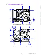
Figure 1.1 MIO-5290L Mechanical Drawing (Top Side) .............. 7
Figure 1.2 MIO-5290 Mechanical Drawing (Bottom Side) ........... 7
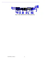
Figure 1.3 MIO-5290U Mechanical Drawing (Coastline) ............. 8
Chapter
2
Installation
............................................9
2.1
Jumpers .................................................................................................. 10
Table 2.1: Jumpers.................................................................... 10
2.2
Connectors.............................................................................................. 10
Table 2.2: Connectors ............................................................... 10
2.3
Locating connectors & block diagram ..................................................... 11
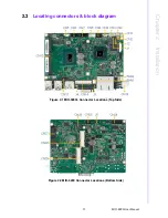
Figure 2.1 MIO-5290L Connector Locations (Top Side)............ 11
Figure 2.2 MIO-5290 Connector Locations (Bottom Side)......... 11
Figure 2.3 MIO-5290U Connector Locations (Coastline)........... 12
2.4
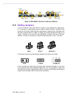
Setting Jumpers ...................................................................................... 12
2.4.1
Clear CMOS (J1) ........................................................................ 13
Table 2.3: Clear CMOS (JP1).................................................... 13
2.4.2
Auto Power On Setting (J2) ........................................................ 13
Table 2.4: Auto Power On Setting (J2)...................................... 13
2.4.3
LCD Power (J3) .......................................................................... 13
Table 2.5: LCD Power (J3) ........................................................ 13
2.4.4
LVDS Panel Power Select (J4) ................................................... 14
Table 2.6: LVDS Panel Power Select (J4)................................. 14
2.4.5
COM2 Setting (J5) ...................................................................... 14
Table 2.7: COM2 Setting (J5).................................................... 14
Chapter
3
AMI BIOS Setup
.................................15
Figure 3.1 Setup program initial screen..................................... 16
3.1
Entering Setup ........................................................................................ 17
3.2
Main Setup .............................................................................................. 17
Figure 3.2 Main setup screen .................................................... 17
3.2.1
System time / System date ......................................................... 17
3.3
Advanced BIOS Features Setup ............................................................. 18
Figure 3.3 Advanced BIOS features setup screen .................... 18
3.3.1
Advantech BIOS Update V1.3 .................................................... 19
Figure 3.4 Advanced BIOS Update screen................................ 19
3.3.2
ACPI Settings.............................................................................. 20
Figure 3.5 ACPI Setting ............................................................. 20
3.3.3
TPM Configuration ...................................................................... 21
Figure 3.6 TPM Configuration.................................................... 21
3.3.4
CPU Configuration ...................................................................... 22
Figure 3.7 CPU Configuration Setting ....................................... 22
Summary of Contents for MIO-5290
Page 7: ...MIO 5290 User Manual vi...
Page 11: ...MIO 5290 User Manual x...
Page 17: ...MIO 5290 User Manual 6 1 3 Block Diagram...
Page 19: ...MIO 5290 User Manual 8 Figure 1 3 MIO 5290U Mechanical Drawing Coastline...
Page 26: ...Chapter 3 3 AMI BIOS Setup...
Page 59: ...MIO 5290 User Manual 48...
Page 60: ...Chapter 4 4 MIOe Installation...
Page 79: ...MIO 5290 User Manual 68...
Page 81: ...MIO 5290 User Manual 70 43 GND 44 NC 45 NC 46 NC 47 NC 48 1 5V 49 NC 50 GND 51 NC 52 3 3VSB...
Page 83: ...MIO 5290 User Manual 72 43 GND 44 NC 45 NC 46 NC 47 NC 48 1 5V 49 NC 50 GND 51 NC 52 3 3VSB...
Page 85: ...MIO 5290 User Manual 74...
Page 89: ...MIO 5290 User Manual 78...
Page 90: ...Appendix C C Watchdog Timer Sample Code...
Page 92: ...81 MIO 5290 User Manual Appendix C Watchdog Timer Sample Code...


