


MOS-1130 User Manual 3
4.1 How to Set Jumpers
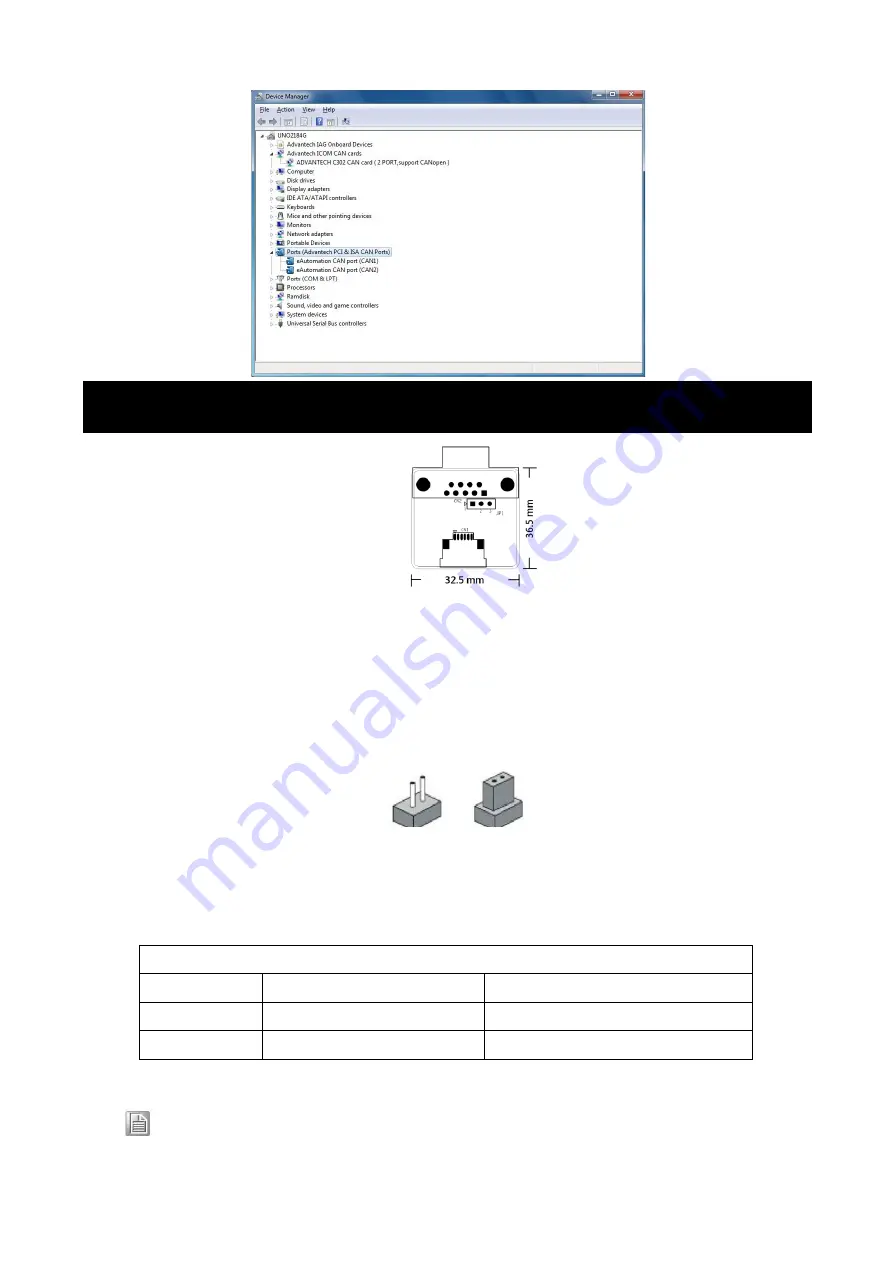
Figure 1 CAN-bus transceiver board silk screen
You configure your card to match the needs of your application by setting jumpers. A jumper is the simplest kind of
electric switch. It consists of two metal pins and a small metal clip (often protected by a plastic cover) that slides over
the pins to connect them. To “close” a jumper you connect the pins with the clip. To “open” a jumper you remove the
clip.
Figure 2 How to set the jumpers
4.2 Terminator Resistor Setup (JP1)
You can set the terminator resistor if necessary to match impedance. Each port has a separate resistor located on its
own transceiver board.
Note!
Table 1: MOS-1130 Terminator Resistor Jumper Setting
is suggested to set the terminator resistor to 120 Ohm to maintain a satisfactory baud rate performance.
4. Jumper and Switch Settings
Table 1: MOS-1130Y-0201E Terminator Resistor Jumper Setting
Status
Value of Terminator Resistor (Ohm)
Pin 2-3
Open mode
None
Pin 1-2
Close mode
120 Ohms


