


MOS-1130 User Manual 4
6. Wiring
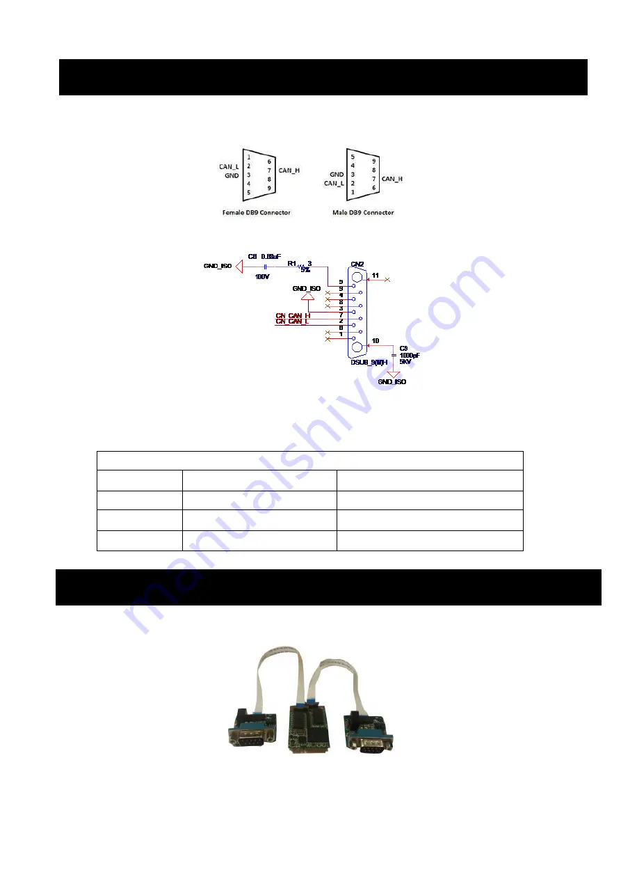
Figure 3 shows the pin assignment for the
card’s male DB-9 connectors and corresponding pin assignments of female
DB-9 connectors of the cable.
Figure 3 MOS-1130Y-0201E DB-9 connector pin assignments
Figure 4 MOS-1130Y-0201E DB-9 connector schematics
The CAN standard supports half
–duplex communication. This means that just two wires are used to transmit and receive
data.
CAN-bus main board has two FPC connectors for wiring to two CAN-bus transceiver boards through
FPC cables. Please ensure to follow Figure 5 and Figure 6 for appropriate wiring in between.
Figure 5 FPC cable wiring
5. Pin Assignments
Table 2: MOS-1130Y-0201E Terminator Resistor Jumper Setting
Pin
Signal
Description
2
CAN_L
LOW-level CAN voltage input/output
3
GND
Ground
7
CAN_H
HIGH-level CAN voltage input/output


