PCE-3029/4129 User Manual
6
1.5
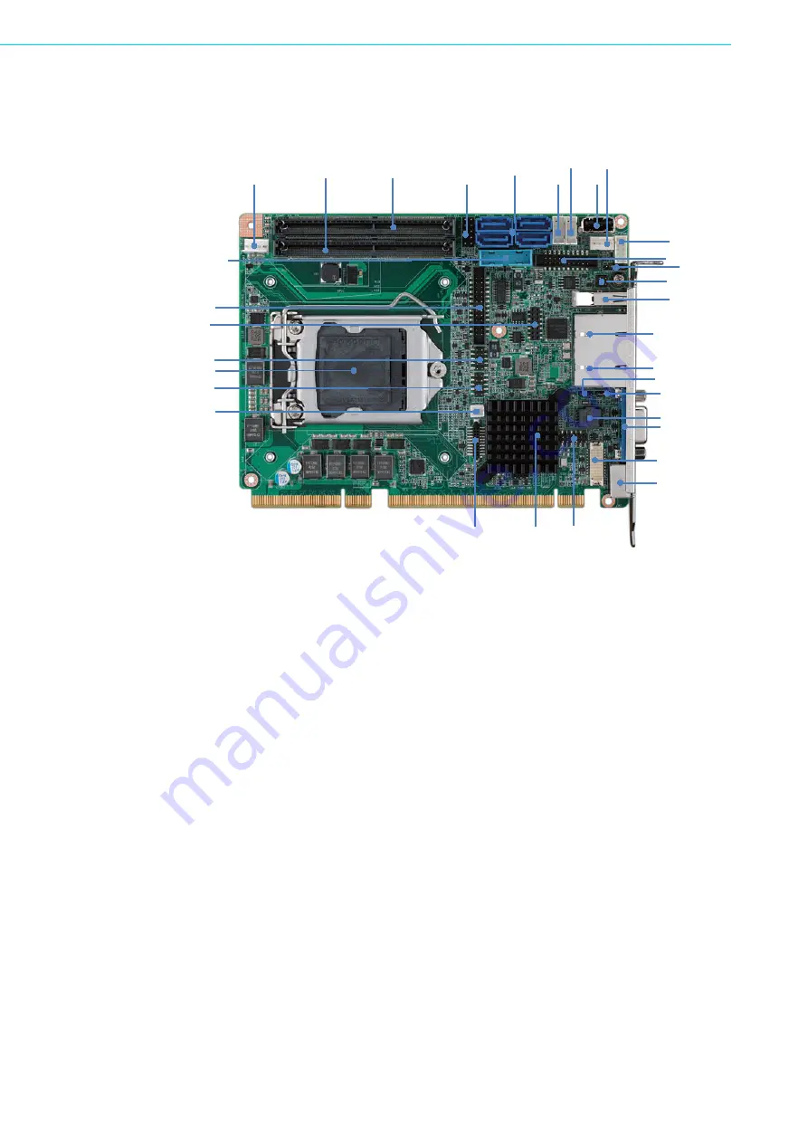
Board Layout: Jumper and Connector
Locations
Figure 1.1 Jumper and connector locations
DIMM B1
DIMM A1
PWR1
FP1
USB45
USB89
USB11
CPU FAN1
USB67
USB1
LAN2
LAN1
BIOS SPI1
VGA1
DVI1
PCH: C236
DP1
JCASE1
LPT1
LPC1
GPIO1
LGA1151
USB23
SATA0 SATA1
SATA3 SATA2
EXPCIE1
LAN LED1
KBMS1
HDAUD1
COM12
JWDT1 JOBS1
JCOMS1
JME1
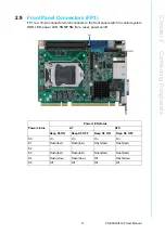
Summary of Contents for PCE-3029
Page 11: ...Chapter 1 1 Hardware Configuration ...
Page 21: ...Chapter 2 2 Connecting Peripherals ...
Page 37: ...Chapter 3 3 AMI BIOS Setup ...
Page 69: ...Chapter 4 4 Value Added Software Services ...
Page 71: ...Chapter 5 5 Chipset Software Installation Utility ...
Page 74: ...PCE 3029 4129 User Manual 64 ...
Page 75: ...Chapter 6 6 Integrated Graphic Device Setup ...
Page 77: ...Chapter 7 7 LAN Configuration ...
Page 79: ...Chapter 8 8 Intel ME ...
Page 81: ...Chapter 9 9 Intel USB 3 0 ...
Page 83: ...Chapter 10 10 SATA RAID Setup ...
Page 85: ...Appendix A A Programming the Watchdog Timer ...
Page 93: ...Appendix B B I O Pin Assignments ...
Page 105: ...Appendix C C Programming the GPIO ...


