background image

PCE-5B06-03A1E Startup Manual  1

Before you begin installing your card, please make sure that 

the following items have been shipped:
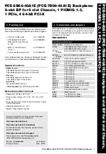
1.  PCE-5B06-03A1E Startup manual 
2.  M4*6*0.7 Round Screws (5 pcs)  p/n: 1939000410
3.  2 years quality warranty card  

p/n: 2190000902

If any of these items are missing or damaged, please con-

tact your distributor or sales representative immediately. 

Standard PC Functions

•  PICMIG 1.3 slots:  

PCE-5B06-03 supports PCE-

5XXX/7XXX CPU boards

•  PCIe slots: 

 PCE-5B06-03  supports one PCIe x 16 slot 

and one PCIe x4

•  32-bit PCI: 

 Three  32  Bit  /  33  MHz  PCI  slot                                                      

•  USB (2.0) support: 

Four Universal Serial Bus ports to 

Backplane

Mechanical and Environment

•  Dimensions: 

80.01 x 325 mm

•  Power supply voltage:

 +12 V, +5 V, -12 V, -5 V, +5 V SBY, 

+3.3 V

•  Power requirements:

 Refer to the CPU Board, add-on 

Card & Peripherals 

•  Operating temperature: 

0 ~ 60° C

•  Weight:

 0.211 kg (weight of board)

PCE-5B06-03A1E Backplane: 6-slot BP for 6 slot Chassis, 1 PIC-

MIG 1.3, 1 x PCIex16, 1 x PCIex4, 3 x 32-bit PCI 

Startup Manual


The board has a number of jumpers that allow you to con-

figure your system to suit your application.

The table below lists the function of each of the jumpers and

connectors.

Jumpers and connectors

Jumpers

Label

Function

PSON1 

ATX / AT Mode Selection


Connectors

Label

Function

SHBA1~SHBD1

PICMG1.3 CPU board slot

PPCIEX4_1

PCIE X4 slot 

PPCIEX16_1

PCIe x 16 slot

PPCI1~PPCI3

32 Bit / 33 MHz PCI Bus slot

EATXPWR1

ATX2.0 24-pin Power Connector

EATX12V1

ATX 12 V Auxiliary 8-pin Power 

Connector

ATX12V1

ATX 12 V 4-pin Power Connector

VOLT1

Alarm board / CMM Power Connector

PWR3V1

ATX 3V 6-pin Power Connector

FAN1

FAN Connector

FAN2

FAN Connector

FAN3

FAN Connector

FAN4

FAN Connector

FAN5   

FAN connector

FANDEC1

FAN speed detector Connector

SMBUS1

SMBus Connector for chassis 

monitor

SMBUS2

SMBus Connector for chassis 

monitor

JFP1

Power and Reset button Connector

IPMB1

IPMB Connector

USB12

Two USB port pin headers

USB34

Two USB port pin headers

  Specifications

  Packing List

For more information on this and other Advantech 

products, please visit our website at:

http://www.advantech.com

http://www.advantech.com/eplatform

For technical support and service, please visit our 

support website at:

http://support.advantech.com

This manual is for PCE-5B06-03A1E series Rev. A1.

Part No. 20065B0600
Print in China

1st Edition

Mar.  2013


Jumpers and Connectors

Summary of Contents for PCE-5B06-00A1E

Page 1: ...headers Mechanical and Environment Dimensions 317 5 x 142 17 mm Power supply voltage 12 V 5 V 12 V 5 V 3 3 V 5VSBY 3 3VSBY Power requirements Refer to the CPU Board add on Card Peripherals Operating...

Page 2: ...for chassis monitor SMBUS2 SMBus Connector for chassis monitor KBMS1 External Keyboard Mouse Connector KBMS2 External Keyboard Mouse Connector JFP1 Power and Reset button Connector IPMB1 IPMB Connecto...

Page 3: ...AT 3 GND USB12 Pin Name 1 USBV0 2 USBV0 3 USBD0 4 USBD1 5 USBD0 6 USBD1 7 GND 8 GND 9 Null 10 GND USB34 Pin Name 1 USBV2 2 USBV2 3 USBD2 4 USBD3 5 USBD2 6 USBD3 7 GND 8 GND 9 Null 10 GND JFP1 Pin Name...

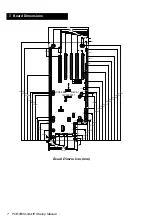
Page 4: ...4 PCE 5B06 00A1E Startup Manual Locating Connectors and Jumpers Mechanical Drawing Locating connectors and Jumpers Board Dimensions...

Page 5: ...PCE 5B06 00A1E Startup Manual 5 Board Diagram Board Diagram...

Page 6: ...suit your application The table below lists the function of each of the jumpers and connectors Jumpers and connectors Jumpers Label Function PSON1 ATX AT Mode Selection Connectors Label Function SHBA1...

Page 7: ...15 GND 16 PSON 17 GND 18 GND 19 GND 20 5 V 21 5 V 22 5 V 23 5 V 24 GND ATX12V1 Pin Name 1 GND 2 GND 3 12 V 4 12 V EATX12V1 Pin Name 1 GND 2 GND 3 GND 4 GND 5 12 V 6 12 V 7 12 V 8 12 V PWR3V1 Pin Name...

Page 8: ...3 PPCI4 IDSEL AD 31 AD 30 AD 29 AD 28 INT A INT B INT C INT D INT A INT B INT C INT D INT A INT B INT C INT D INT A INT B INT C INT D INT A INT B INT C INT D 1 2 3 1 2 3 FANDEC1 Pin Name 1 FANIO1 2 FA...

Page 9: ...ATX12V1 SMBUS2 SMBUS1 JFP1 PSON1 EATX12V1 EAXPWR1 VOLT1 FAN1 FAN2 FAN3 FAN4 IPMB1 PWR3V1 FAN5 KEY KEY KEY KEY PSON1 FAN3 IPMB1 FAN4 VOLT1 FAN2 FAN1 SHBA1 SHBB1 SHBC1 SHBD1 FAN5 SMBUS1 PWR3V1 EATX12V1...

Page 10: ...P1PCI USBX4 IPMI POWER PICMG 1 3 CONNECTOR C SMBUS X2 LAN X2 SATA X2 USB X4 PICMG 1 3 CONNECTOR B PCI EXPRESS X8 PICMG 1 3 CONNECTOR A PCI EXPRESS X8 AND X4 PPCIeX16_1 PCI E x16 PCI E x4 SHB PPCIeX4_1...

Page 11: ...imensions 4 00 x13 10 00 x13 R2 00 3 00 266 00 101 57 16 12 16 51 111 01 3 00 x5 327 66 314 96 292 46 260 35 250 66 180 16 170 81 165 16 10 16 107 16 268 84 177 15 111 11 41 28 45 45 142 17 125 64 105...

Page 12: ...n 1939000410 2 years quality warranty card p n 2190000902 For more information on this and other Advantech products please visit our website at http www advantech com http www advantech com eplatform...

Page 13: ...US1 SMBUS2 PWR_LED SPK SMBUS HDD_LED RESET PWRBTN 19CK5B0601 PCIXCAP PSON1 ATX AT Mode Select Jumper Setting 2 3 SHORT 1 2 SHORT GF_PS_ON PSP_PS_ON GND 12V 12V 3 3V 5V 5V GND GND 5VSB GND 12V GND 3 3V...

Page 14: ...GND 18 GND 19 GND 20 5V 21 5V 22 5V 23 5V 24 GND ATX12V1 Pin Name 1 GND 2 GND 3 12V 4 12V EATX12V1 Pin Name 1 GND 2 GND 3 GND 4 GND 5 12V 6 12V 7 12V 8 12V PWR3V1 Pin Name 1 3 3V 2 3 3V 3 3 3V 4 GND...

Page 15: ...KBMS2 Pin Name 1 KBCLK 2 KBDAT 3 MSDAT 4 GND 5 5V 6 MS_CLK IPMB1 Pin Name 1 IPMB_CLK 2 IPMB_DAT 3 GND USB12 Pin Name 1 USBV0 2 USBV0 3 USBD0 4 USBD1 5 USBD0 6 USBD1 7 GND 8 GND 9 Null 10 GND USB34 Pin...

Page 16: ...IDSEL AD 31 AD 30 AD 29 AD28 Interrupt INTA INTD INT C INT B INT A Pin INTB INTA INT D INT C INT B Route INTC INTB INT A INT D INT C INTD INTC INT B INT A INT D 5 Jumper Settings PSON1 ATX AT Mode Se...

Page 17: ...PCE 5B06 04A1E Startup Manual 6 Board Diagram 6 Board Diagram...

Page 18: ...2V 3 3V 5V 5V GND GND 5VSB GND 12V GND 12V GND GND 5V 3 3V GND 12V REV A1 01 2 PCE 5B06 JUMPERJ3 MODE FPIO LAN 1 2 PULLUP 2 3 GND M66EN J2 66 33 PCI MHZ 1 2 SHORT 2 3 SHORT AT ATX MODE PINROUTE INTERR...

Page 19: ...6 0 7 Round Screws 15 pcs p n 1939000410 2 years quality warranty card p n 2190000902 For more information on this and other Advantech products please visit our website at http www advantech com http...

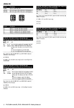
Page 20: ...lection J6 Primary 2 PCI PCI X bus capability selection P1PCIX1 P1PCIX2 PCI X Bus Capability and Frequency Setting when they are set to PCI X mode PCI X MHz J3 J2 66 1 2 PCI X mode is backward compati...

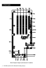
Page 21: ...3 PCE 5B06 40A1E PCE 7B06 40A1E Startup Manual Board Layout Jumper and Connector Locations 3 Board Layout...

Page 22: ...SON 17 GND 18 GND 19 GND 20 5V 21 5V 22 5V 23 5V 24 GND ATX12V1 Pin Name 1 GND 2 GND 3 12V 4 12V EATX12V1 Pin Name 1 GND 2 GND 3 GND 4 GND 5 12V 6 12V 7 12V 8 12V PWR3V1 Pin Name 1 3 3V 2 3 3V 3 3 3V...

Page 23: ...1 5V 2 C SMBBUS 3 C SMBDAT 4 GND IPMB1 Pin Name 1 IPMB_CLK 2 IPMB_DAT 3 GND USB12 Pin Name 1 USBV0 2 USBV0 3 USBD0 4 USBD1 5 USBD0 6 USBD1 7 GND 8 GND 9 Null 10 GND USB34 Pin Name 1 USBV2 2 USBV2 3 U...

Page 24: ...Settings PSON1 ATX AT Mode Selection Jumper Setting Function 1 2 closed pins AT mode 2 3 closed pins ATX mode default JP1VIO1 Pin Name 1 VCC 2 VCC 3 VCC 4 PB_VIO 5 PB_VIO 6 PB_VIO 7 VCC3 8 VCC3 9 VCC3...

Page 25: ...RESS X8 AND X4 PICMG 1 3 CONNECTOR C USBX4 SATAX2 LANX2 IPMBX1 PCI EXPRESS X8 PICMG 1 3 CONNECTOR B PCI EXPRESS X16 X8 X4 COLAY PCI X CH B 64 bit 100MHz PCI X CH A 64 bit 100MHz X4 X8 X8 PCI X CH B 64...

Page 26: ...8 PCE 5B06 40A1E PCE 7B06 40A1E Startup Manual Board Dimensions mm 8 Board Dimensions...

Reviews: