PCIE-1840 User Manual
16
3.3.2
Trigger Type
The PCIE-1840 supports two types of triggers: start triggers and stop triggers.
The returned data consists of samples acquired between a start trigger and a stop
trigger. That is, only data acquired after the start trigger occurred and before the stop
trigger occurred are returned.
Both start triggers and stop triggers can be delayed. When the delay number is
applied to a trigger, the trigger is effective only when the number of samples has
reached after the trigger occurs. For example, if delay number of 5 is applied to the
start trigger, the returned data will consist of samples acquired after the start trigger
occurred except the first 5 samples. If delay number of 3 is applied to the stop trigger,
the returned data will consist of samples acquired before the stop trigger occurred
plus 3 samples acquired after the stop trigger.
Both triggers can be configured independently, and can be set to use a variety of
sources, both analog and digital. Triggers can be configured to occur on either the
rising or falling edge of a signal. Moreover, analog triggers support other modes of
operation, including triggering on edges with hysteresis, and triggering when a signal
enters or leaves a predefined window. Since all three types of triggers are configured
independently, alternate edges of a signal can be used for different types of triggers.
During repetitive triggering on a waveform, you might observe jitter because of the
uncertainty of where a trigger level falls compared to the actual digitized data.
Although this trigger jitter is never greater than one sample period, it might be signifi-
cant when the sample rate is only twice the bandwidth of interest. This jitter usually
has no effect on data processing, and you can decrease this jitter by sampling at a
higher rate.
3.3.2.1
Digital Trigger Connections
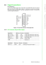
You can configure the PCIE-1840 to trigger in response to digital signals on DTRG0
or DTRG1 pin of the HDMI connector, located on the device front panel. The trigger
circuit can respond either to a rising or a falling edge. The trigger signal must comply
to 3.3 V or 5 V TTL voltage levels.
A diagram showing the DRTG input configuration of the PCIE-1840 is shown below
with a signal source.
Figure 3.2 Digital Trigger Signal Connection
Summary of Contents for PCIE-1840
Page 1: ...User Manual PCIE 1840 4 ch 16Bit 125 MS s High Speed Data Acquisition PCI Express Card ...
Page 4: ...PCIE 1840 User Manual iv ...
Page 12: ...PCIE 1840 User Manual 6 ...
Page 13: ...Chapter 2 2 Installation ...
Page 18: ...PCIE 1840 User Manual 12 ...
Page 26: ...PCIE 1840 User Manual 20 ...
Page 27: ...Appendix A A Specifications ...
Page 35: ...Appendix B B Block Diagram ...


