background image

User Manual

PCM-9362

3.5" Biscuit with Intel® Atom® 
N450/D510, VGA, LVDS, 2 Giga-
LAN, USB, SATA, Mini PCIe and 
SSD

Summary of Contents for PCM-9362 Series

Page 1: ...User Manual PCM 9362 3 5 Biscuit with Intel Atom N450 D510 VGA LVDS 2 Giga LAN USB SATA Mini PCIe and SSD...

Page 2: ...ents of the rights of third parties which may result from its use Acknowledgements AMI is a trademark of AMI Software International Inc Intel is a trademark of Intel Technologies Inc IBM PC AT PS 2 an...

Page 3: ...used etc Note anything abnormal and list any onscreen messages you get when the problem occurs 2 Call your dealer and describe the problem Please have your manual product and any helpful information...

Page 4: ...ardbus MIO 6260 MIO module w 4 x USB 2 x COM 1 x LAN Part Number Description 1700006291 SATA cable 30cm 1703060191 Keyboard mouse cable 1 6P 2 0 M DIN 6P F 2 19cm 1700000265 WIRE ATX 20P M 12P F 10CM...

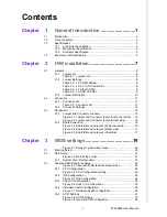
Page 5: ...nector layout Component side 15 Figure 2 2 Jumper and Connector layout Solder side 15 2 3 2 Board Dimension 16 Figure 2 3 Board Dimension layout Component side 16 Figure 2 4 Board Dimension layout Sol...

Page 6: ...on 41 3 7 Advanced Chipset Settings 42 Figure 3 23Advanced Chipset Settings 42 3 7 1 North Bridge Chipset Configuration 43 Figure 3 24North Bridge Configuration 43 Figure 3 25Video function configurat...

Page 7: ...A 16 CN16 18 bits LVDS Panel 74 Table A 17 CN17 LAN 75 Table A 18 CN18 LAN1 75 Table A 19 CN19 LAN2 76 Table A 20 CN20 Power Switch Low Active 76 Table A 21 CN11 LPT 76 Table A 22 CN22 Standby Power...

Page 8: ...PCM 9362 User Manual viii...

Page 9: ...Chapter 1 1 General Introduction This chapter gives background information on the PCM 9362 Sections include Introduction Product feature Specifications...

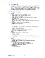
Page 10: ...ash Card TYPE I II Watchdog Timer Single chip Watchdog 255 level interval timer setup by soft ware Expansion Interface Supports 1 x Mini PCIe device Battery Lithium 3 V 210 mAH I O I O Interface 2 x S...

Page 11: ...DE Interface ICH8M Supports one CF device H D Codec ALC888 I F ICH8M supports Support for HD codec Up to 2 1 channel of PCM audio output Connectors Line out Line in Mic in Pin header 2 5P M 2 0 mm Con...

Page 12: ...r Hirose DF13 type 20 pin CRT connector D SUB15 at coastline LAN LAN1 Intel 82567 LAN2 Intel 82583V Compliant with IEEE 802 3 IEEE 802 3u IEEE 802 3x IEEE 8023y IEEE 802 ab Support 1000Mbps Connectors...

Page 13: ...E 5 V 2 31 A PCM 9362N S6A1E 12 V 0 87 A PCM 9362D S6A1E 12 V 0 91 A Max in HCT PCM 9362NC S6A1E 5 V 2 36 A PCM 9362N S6A1E 12 V 1 01 A PCM 9362D S6A1E 12 V 1 17 A 1 3 3 3 RTC Battery Typical Voltage...

Page 14: ...PCM 9362 User Manual 6...

Page 15: ...ins the setup procedures of the PCM 9362 hard ware including instructions on setting jumpers and connecting peripherals switches indicators and mechanical drawings Be sure to read all safety precautio...

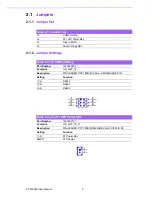
Page 16: ...SEL Table 2 2 J2 COM2 Setting Part Number 1653003260 Footprint HD_3x2P_79 Description PIN HEADER 3 2P 180D M 2 0mm SMD SOUARE PIN Setting Function 1 2 RS232 3 4 RS485 5 6 RS422 Table 2 3 J3 AT ATX Po...

Page 17: ...03101 Footprint HD_3x1P_79_D Description PIN HEADER 3 1P 180D M 2 0mm DIP SQUARE W O Pb Setting Function 1 2 Normal 2 3 Clear CMOS Table 2 5 J5 PAN VOL SEL Part Number 1653003101 Footprint HD_3x1P_79_...

Page 18: ...and 3 In this case you would connect either pins 1 and 2 or 2 and 3 The jumper settings are schematically depicted in this manual as follows A pair of needle nose pliers may be helpful when working wi...

Page 19: ...4 CN8 AT ATX Power Input CN9 MIO 2 0 CN10 PS2 CN11 SMBus CN12 COM2 CN13 Inverter Power Output CN14 Internal USB CN15 Internal USB CN16 18 bits LVDS Panel CN17 LAN Option CN18 LAN1 CN19 LAN2 CN20 Power...

Page 20: ...LED indicator 2 2 2 5 Power Reset Button CN23 Momentarily pressing the reset button will activate a reset The switch should be rated for 10 mA 5 V 2 2 2 6 Power Connectors Main power connector CN6 CN8...

Page 21: ...CM 9362 can provide 5 V and 12 V and signal to LCD inverter board via CN13 2 2 2 11 USB Connectors CN14 CN15 CN24 CN25 The board provides up to six USB Universal Serial Bus ports This gives complete P...

Page 22: ...or CN28 CN29 PCI Express Mini Card also known as Mini PCI Express Mini PCIe and Mini PCI E is a replacement for the Mini PCI form factor based on PCI Express It is developed by the PCI SIG The host de...

Page 23: ...PCM 9362 User Manual Chapter 2 H W installation 2 3 Mechanical 2 3 1 Jumper and Connector Location Figure 2 1 Jumper and Connector layout Component side Figure 2 2 Jumper and Connector layout Solder s...

Page 24: ...PCM 9362 User Manual 16 2 3 2 Board Dimension Figure 2 3 Board Dimension layout Component side...

Page 25: ...17 PCM 9362 User Manual Chapter 2 H W installation Figure 2 4 Board Dimension layout Solder side Figure 2 5 Board Dimension layout Coastline...

Page 26: ...PCM 9362 User Manual 18...

Page 27: ...Chapter 3 3 BIOS settings...

Page 28: ...nfiguration This information is stored in battery backed CMOS so it retains the setup information when the power is turned off 3 1 Entering Setup Turn on the computer and check for the patch code If t...

Page 29: ...the options that can be configured Grayed out options cannot be configured options in blue can The right frame displays the key legend Above the key legend is an area reserved for a text message When...

Page 30: ...the left frame of the screen such as CPU Configuration to go to the sub menu for that item You can display an Advanced BIOS Setup option by highlighting it using the Arrow keys All Advanced BIOS Setu...

Page 31: ...No Execution page protection technol ogy Hyper Threading Technology This item allows you to enable or disable Intel Hyper Threading technology Intel SpeedStep tech When set to disabled the CPU runs at...

Page 32: ...tec tion of IDE device Type Select the type of SATA driver Not Installed Auto CD DVD ARMD LBA Large Mode Enables or Disables the LBA mode Block Multi Sector Transfer Enables or disables data multi sec...

Page 33: ...rt 4 address This item allows you to select serial port1 port4 of base addresses Serial Port1 Port2 Port3 Port 4 IRQ This item allows you to select serial port1 port4 of IRQ RS 485 Control for SP2 Thi...

Page 34: ...6 3 3 4 Hardware Health Configuration Figure 3 7 Hardware health configuration H W Health Function This item allows you to control H W monitoring Temperature Voltage show CPU System Temperature Vcore...

Page 35: ...27 PCM 9362 User Manual Chapter 3 BIOS settings 3 3 5 ACPI Settings Figure 3 8 ACPI Settings...

Page 36: ...28 3 3 5 1 General ACPI Configuration Figure 3 9 General ACPI Configuration Suspend mode Select the ACPI state used for system suspend Report Video on S3 Resume This item allows you to invoke VA BIOS...

Page 37: ...uration ACPI Version Features This item allows you to enable RSDP pointers to 64 bit fixed system description tables ACPI APIC support Include APIC table pointer to RSDT pointer list AMI OEMB table In...

Page 38: ...tion Energy Lake Feature Allows you to configure Intel s Energy Lake power management technology APIC ACPI SCI IRQ Enable Disable APIC ACPI SCI IRQ USB Device Wakeup From S3 S4 Enable Disable USB Devi...

Page 39: ...l Chapter 3 BIOS settings 3 3 6 AHCI Configuration Figure 3 12 AHCI Configuration AHCI Port0 Port1 While entering setup BIOS auto detects the presence of IDE devices This displays the status of auto d...

Page 40: ...f after power failure the On setting boots up the system after failure and the Last State returns the system to the status just before power failure Video Power Down Mode Power down video in suspend o...

Page 41: ...settings 3 3 8 Event Log Configuration Figure 3 14 Event Log Configuration View Event Log View all unread events on the event Log Mark all events as read Mark all unread events as read Clear Event Lo...

Page 42: ...PCM 9362 User Manual 34 3 3 9 MPS Configuration Figure 3 15 MPS Configuration MPS Revision This item allows you to select MPS reversion...

Page 43: ...35 PCM 9362 User Manual Chapter 3 BIOS settings 3 3 10 Smbios Configuration Figure 3 16 Smbios Configuration Smbios Smi Support SMBIOS SMI wrapper support for PnP function 50h 54h...

Page 44: ...2 0 Controller Mode This item allows you to select HiSpeed 480Mbps or FullSpeed 12Mpbs BIOS EHCI Hand Off This is a workaround for OS without EHCI hand off support The EHCI ownership change should cl...

Page 45: ...guration USB Mass Storage Reset Delay Number of sends POST wait for the USB mass storage device after start unit com mand Emulation Type If Auto USB devices less than 530MB will be emulated as a flopp...

Page 46: ...Fail Safe default setting is No Plug Play O S When set to No BIOS configures all the device in the system When set to Yes and if you install a Plug and Play operating system the operating system conf...

Page 47: ...This item allows you respectively assign an interruptive type for IRQ 3 4 5 7 9 10 11 DMA Channel 0 1 3 5 6 7 When set to Available will specify which DMA is available to be used by PCI PnP devices Wh...

Page 48: ...Enabled an OEM Logo is shown instead of POST messages AddOn ROM Display Mode Set display mode for option ROM Bootup Num Lock Select the Power on state for Numlock PS 2 Mouse Support Select support for...

Page 49: ...IOS setup menu All Security Setup options such as password protection and virus protection are described in this section To access the sub menu for the following items select the item and press Enter...

Page 50: ...PCM 9362 User Manual 42 3 7 Advanced Chipset Settings Figure 3 23 Advanced Chipset Settings...

Page 51: ...Configure DRAM Timing by SPD This item allows you to enables or disable detection by DRAM SPD Memory Hole This item allows you to free 15MB 16MB of memory size for some ISA devices Initate Graphic Aad...

Page 52: ...VMT FIXED Memory Specify the amount of DVMT FIXED system memory to allocate for video memory Boot Display Device Select boot display device at post stage Flat Panel Type This item allows you to select...

Page 53: ...controller Enables or disables the internal LAN controller Internal LAN Bootroom Enables or disables internal LAN boot GbE controller Enables or disables the GbE controller GbE LAN Boot Enables or di...

Page 54: ...xit menu and press Enter The following message appears Save Configuration Changes and Exit Now Ok Cancel 2 Select Ok or cancel 3 8 2 Discard Changes and Exit Select this option to quit Setup without m...

Page 55: ...em configuration problems Select Load Optimal Defaults from the Exit menu and press Enter 3 8 4 Load Fail Safe Defaults The PCM 9362 automatically configures all setup options to fail safe settings wh...

Page 56: ...PCM 9362 User Manual 48...

Page 57: ...Chapter 4 4 S W Introduction Installation...

Page 58: ...chipset folder on the CD ROM 4 3 Value Added Software Services Software API An interface that defines the ways by which an application program may request services from libraries and or operating sys...

Page 59: ...the I2 C protocol has been taken care of by SUSI Instead of asking application programmers to figure out the strict timing requirements in the I2 C protocol the I2 C API in SUSI can be used to control...

Page 60: ...tem Throttling Refers to a series of methods for reducing power consumption in computers by lowering the clock frequency APIs allow the user to lower the clock from 87 5 to 12 5 4 3 3 SUSI Utilities 4...

Page 61: ...er has executed the SUSI Library and related files for Windows XP can be found in the target installation directory The files are listed in the following table The following section illustrates the in...

Page 62: ...TRELEASEDIR GPIO exe NK S SMBUS exe _FLATRELEASEDIR SMBUS exe NK S Place the three files into any files directory Build your new Windows CE operating system 4 3 5 SUSI Sample Programs Sample Programs...

Page 63: ...atform does not support such functions For a complete support list please refer to Appendix A We describe the steps to test all functions of this application GPIO When the application is executed it w...

Page 64: ...radio button Multiple Pins Key in the pin number from 0x01 to 0x0F to choose the multiple pin num bers to write the value of the output pin The pin numbers are ordered bit wise i e bit 0 stands for GP...

Page 65: ...f the watchdog as follows Read a byte Click the radio button Access a byte Key in the slave device address in the Slave address field Key in the register offset in the Register Offset field Click the...

Page 66: ...m the device will be divided from each other by commas and be shown in the Result field Write Multiple bytes Click the radio button Access multiple bytes Key in the slave device address in the Slave a...

Page 67: ...application is executed it will display watchdog information in the WATCH DOG INFORMATION group box It displays max timeout min timeout and timeout steps in milliseconds For example a 1 255 seconds w...

Page 68: ...ardware monitoring data values will be displayed If certain data values are not supported by the platform the correspondent data field will be grayed out with a value of 0 For More detail PCM 9362 sof...

Page 69: ...Appendix A A PIN Assignments...

Page 70: ...t HD_5x2P_79_BOX Description BOX HEADER SMD 5 2 180D M 2 0mm Pin Pin Name 1 LOUTR 2 LINR 3 GND 4 GND 5 LOUTL 6 LINL 7 GND 8 GND 9 MIC1R 10 MIC1L Table A 2 CN2 SATA Part Number 1654002320 Footprint FOX...

Page 71: ...7V S33T5 Description Serial ATA 7P 1 27 90D M SMD LD1107V S33T5 Pin Pin Name 1 GND 2 TX 3 TX 4 GND 5 RX 6 RX 7 GND Table A 4 CN4 GPIO Part Number 1653005261 Footprint HD_5x2P_79 Description PIN HEADER...

Page 72: ...M Description WAFER BOX 2 0mm 6P 180D M W LOCK Pin Pin Name 1 5V 2 GND 3 Power LED 4 Power LED 5 HDD LED 6 HDD LED Table A 6 CN6 12V AT Power Input Part Number 1655404090 Footprint ATXCON 2X2 42 Descr...

Page 73: ...M3 COM4 Part Number 1653210260 Footprint HD_10x2P_79_BOX Description BOX HEADER 10 2P 180D M 2 0mm SMD W O Pb Pin Pin Name 1 DCD3 2 DSR3 3 RXD3 4 RTS3 5 TXD3 6 CTS3 7 DTR3 8 RI3 9 GND 10 GND 11 DCD4 1...

Page 74: ...able 1700000265 Table A 8 CN8 AT ATX Power Input Part Number 1655412090 Footprint ATXCON 2X6V 42 Description Power CONN 6 2P 180D M DIP W Fixed Lock Pin Pin Name 1 GND 2 5V 3 5V 4 GND 5 5V 6 5V 7 GND...

Page 75: ...e A1 USB_OC A2 USB_D A3 USB_D A4 GND A5 LPC_CLK48M A6 GPIO1 A7 GPIO2 A8 LPC_SUSCLK A9 LPC_DRQ 0 A10 Reserved A11 AD0 A12 AD1 A13 AD2 A14 AD3 A15 AD4 A16 AD5 A17 AD6 A18 AD7 A19 CBE 0 A20 AD8 A21 AD9 A...

Page 76: ...D A58 PCIE_CLK1 A59 PCIE_CLK1 A60 GND A61 PCIE_RST A62 Reserved A63 Reserved A64 Reserved A65 GND A66 SDVO_CLK A67 SDVO_CLK A68 GND A69 SDVO_BLUE A70 SDVO_BLUE A71 GND A72 SDVO_GREEN A73 SDVO_GREEN A7...

Page 77: ...B23 AD22 B24 AD23 B25 CBE 3 B26 AD24 B27 AD25 B28 AD26 B29 AD27 B30 AD28 B31 AD29 B32 AD30 B33 AD31 B34 INTC B35 INTD B36 GNT0 B37 GNT1 B38 GNT2 B39 PCIRST B40 Ring B41 Serial IRQ B42 GND B43 PCIE_RX...

Page 78: ...B61 PCIE_WAKE B62 ACPI_S3 B63 ACPI_S5 B64 Reserved B65 GND B66 SDVO_CLDAT B67 SDVO_CLCLK B68 GND B69 SDVO_FLDSTALL B70 SDVO_FLDSTALL B71 GND B72 SDVO_TVCLKIN B73 SDVO_TVCLKIN B74 GND B75 SDVO_INT B76...

Page 79: ...rt Number 1655306020 Footprint WHL6V 2M Description WAFER BOX 2 0mm 6P 180D M W LOCK Pin Pin Name 1 KBCLK 2 KBDAT 3 MSCLK 4 GND 5 5V 6 MSDAT Table A 11 CN11 SMBus Part Number 1655904020 Footprint FPC4...

Page 80: ...HEADER SMD 7 2P 180D M 2 0mm Pin Pin Name 1 DCD 2 DSR 3 RXD 4 RTS 5 TXD 6 CTS 7 DTR 8 RI 9 GND 10 GND 11 422 485TX 12 422 485TX 13 422RX 14 422RX Table A 13 CN13 Inverter Power Output Part Number 1655...

Page 81: ...5260 Footprint HD_5x2P_79_N10 Description PIN HEADER 2 5P 180D M 2 0mm SMD IDIOT PROOF Pin Pin Name 1 5V 2 5V 3 A_D 4 B_D 5 A_D 6 B_D 7 GND 8 GND 9 GND Table A 15 CN15 Internal USB Part Number 1653005...

Page 82: ...3910261 Footprint SPH10X2 Description CONN SMD 10 2P 180D M DF13 20DP 1 25V 91 HRS Pin Pin Name 1 GND 2 GND 3 LVDS0_D0 4 NC 5 LVDS0_D0 6 NC 7 LVDS0_D1 8 NC 9 LVDS0_D1 10 NC 11 LVDS0_D2 12 NC 13 LVDS0_...

Page 83: ...HONE JACK RJ45 28P DIP Gold flash RTB 19GB9J1A Pin Pin Name 1 TX 10 100 BI_DA GHz 2 TX 10 100 BI_DA GHz 3 RX 10 100 BI_DB GHz 4 BI_DC GHz 5 BI_DC GHz 6 RX 10 100 BI_DB GHz 7 BI_DD GHz 8 BI_DD GHz Tabl...

Page 84: ...le A 20 CN20 Power Switch Low Active Part Number 1655302020 Footprint WF_2P_79_BOX_R1_D Description WAFER BOX 2P 180D M 2 0mm W Lock Pin Pin Name 1 PSIN 2 GND Table A 21 CN11 LPT Part Number 165321326...

Page 85: ...700001531 13 D5 14 GND 15 D6 16 GND 17 D7 18 GND 19 ACK 20 GND 21 BUSY 22 GND 23 PE 24 GND 25 SLCT 26 NC Table A 22 CN22 Standby Power Input Part Number 1655303020 Footprint WHL3V 2M Description WAFER...

Page 86: ...655302020 Footprint WF_2P_79_BOX_R1_D Description WAFER BOX 2P 180D M 2 0mm W Lock Pin Pin Name 1 RESET 2 GND Table A 24 CN24 External USB Part Number 1654904105 Footprint USB V 4A Description USB CON...

Page 87: ...4904105 Footprint USB V 4A Description USB CON 4P 90D F DIP A TYPE RoHS Pin Pin Name 1 5V 2 D 3 D 4 GND Table A 26 CN26 COM1 Part Number 1654000056 Footprint DBCOM VM5MS Description D SUB CON 9P 90D M...

Page 88: ...A 27 CN27 VGA Part Number 1654000055 Footprint DBVGA VF5MS Description D SUB Conn 15P 90D F DIP 070242FR015S200ZU Pin Pin Name 1 RED 2 GREEN 3 BLUE 4 NC 5 GND 6 GND 7 GND 8 GND 9 NC 10 GND 11 NC 12 D...

Page 89: ...PCM 9362 User Manual Appendix A PIN Assignments Table A 28 CN28 Mini PCIE lock Part Number 1654002539 Footprint FOX_AS0B226 S68K7F_HOLDER Description MINI PCI Express LATCH 52P 90D SMD 6 8mm Pin Pin N...

Page 90: ...Pin Pin Name 1 WAKE 2 3 3V or 3 3VSB 3 NC 4 GND 5 NC 6 1 5V 7 CLKREQ 8 NC 9 GND 10 NC 11 REFCLK 12 NC 13 REFCLK 14 NC 15 GND 16 NC 17 NC 18 GND 19 NC 20 NC 21 GND 22 PERST 23 PERn0 24 3 3VSB 25 PERp0...

Page 91: ...83 PCM 9362 User Manual Appendix A PIN Assignments 43 GND 44 NC 45 NC 46 NC 47 NC 48 1 5V 49 NC 50 GND 51 NC 52 3 3V or 3 3VSB 53 NC 54 NC 55 GND 56 GND Table A 29 CN29 Mini PCIE slot...

Page 92: ...mm STD SMD WO Pb Pin Pin Name 1 VREF 2 GND 3 GND 4 DQ59 5 DQ63 6 DQ58 7 DQ62 8 GND 9 GND 10 DM7 11 DQS 7 12 GND 13 DQS7 14 DQ57 15 GND 16 DQ56 17 DQ61 18 GND 19 DQ60 20 DQ51 21 GND 22 DQ50 23 DQ55 24...

Page 93: ...QS5 52 DM5 53 GND 54 GND 55 DQ45 56 DQ41 57 DQ44 58 DQ40 59 GND 60 GND 61 DQ39 62 DQ35 63 DQ38 64 DQ34 65 GND 66 GND 67 DM4 68 DQS 4 69 NC 70 DQS4 71 GND 72 GND 73 DQ37 74 DQ33 75 DQ36 76 DQ32 77 GND...

Page 94: ...8V 104 1 8V 105 A10 106 BA1 107 BA0 108 RAS 109 WE 110 SCS 0 111 1 8V 112 1 8V 113 CAS 114 ODT0 115 SCS 1 116 A13 117 1 8V 118 1 8V 119 ODT1 120 NC 121 GND 122 GND 123 DQ31 124 DQ27 125 DQ30 126 DQ26...

Page 95: ...147 DM2 148 DQS2 149 GND 150 GND 151 DQ21 152 DQ17 153 DQ20 154 DQ16 155 GND 156 GND 157 DQ15 158 DQ11 159 DQ14 160 DQ10 161 GND 162 GND 163 NC 164 CK0 165 GND 166 CK0 167 DQS 1 168 GND 169 DQS1 170...

Page 96: ...PCM 9362 User Manual 88 184 GND 185 DM0 186 DQS 0 187 GND 188 DQS0 189 DQ5 190 GND 191 DQ4 192 DQ1 193 GND 194 DQ0 195 SDA 196 GND 197 SCL 198 SA0 199 3 3V 200 SA1 Table A 30 CN30 DDR2 SODIMM...

Page 97: ...n IC SKT 8P SMD WO Pb C ACA SPI 004 K01 Pin Pin Name 1 CE 2 SO 3 WP 4 GND 5 SI 6 SCK 7 HOLD 8 3 3V Table A 32 CN32 CF Part Number 1653002919 Footprint CF_50P_CFCMD 35T15W100 Description CF Type2 Conn...

Page 98: ...PCM 9362 User Manual 90 17 GND 18 A02 19 A01 20 A00 21 D00 22 D01 23 D02 24 NC 25 CD2 26 CD1 Table A 32 CN32 CF...

Page 99: ...91 PCM 9362 User Manual Appendix A PIN Assignments...

Page 100: ...tions are subject to change without notice No part of this publication may be reproduced in any form or by any means electronic photocopying recording or otherwise without prior written permis sion of...

Reviews: