PCM-9381 Startup Manual
3
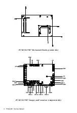
PCM-9381/9387 Mechanical Drawing (component side)
J6: LCD Power
Pin
Signal
1-2
+5V
2-3(*)
+3.3V
*: Default
J8: AT/ATX Power Setting
Setting
Function
J8(1-2)
AT Power (**)
None(*)
ATX Power
*: Default
**: While use AT power, the standby power connector should
be connected to 5V(Please refer to user’s manual Appendix
D).
1
2
3
1
2
3
JP1: PCI VIO
Description PIN HEADER 2*1P 180D (M) SQUARE 2.0mm
Setting
Function
1-2 5V
2-3
3.3V
1
2
3
1
2
3


