PPC-L126 User’s Manual
10
Chapter 2 System Setup
2.1 A Quick Tour of the Panel PC
Before you start to set up the panel PC, take a moment to become familiar
with the locations and purposes of the controls, drives, connectors and
ports, which are illustrated in the figures below.
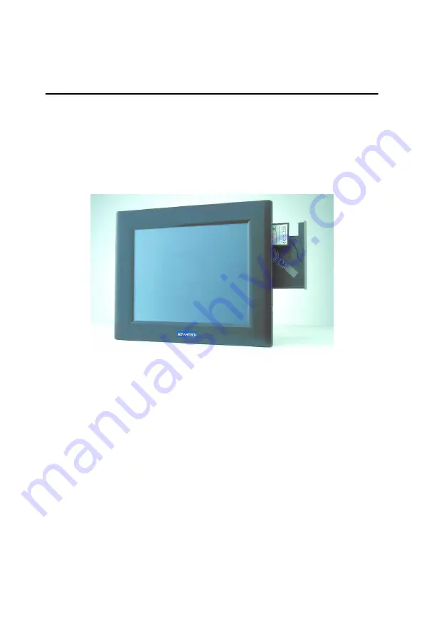
When you place the panel PC upright on the desktop, its front panel
appears as shown in Figure 2-1.
When you turn the panel PC around and look at its rear cover, you will
find the I/O section as shown in Fig. 2-2. (The I/O section includes vari-
ous I/O ports, including serial ports, parallel port, the Ethernet port, USB
ports, the Line-in/Line-out jack, and so on.) The battery door cover is at
the bottom of the panel PC, as shown in Fig. 2-4
Figure 2.1: Front view of PPC-L126 panel PC
Summary of Contents for PPC-L126
Page 1: ...PPC L126 VIA Eden Processor based Fanless Panel PC with 12 1 TFT LCD Users Manual...
Page 8: ...PPC L126 User s Manual viii...
Page 19: ...7 Chapter1 1 4 Dimensions Figure 1 1 Dimensions of PPC L126...
Page 20: ...PPC L126 User s Manual 8...
Page 28: ...PPC L126 User s Manual 16...
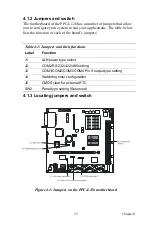
Page 37: ...25 Chapter4 Figure 4 2 Connectors on the PPC L126 motherboard...
Page 47: ...35 Chapter5 5 a Select Network Adaptors b Click Next 6 a Click Have Disk...
Page 49: ...37 Chapter5 9 a Choose Next 10 a Click Finish...
Page 56: ...PPC L126 User s Manual 44 2 a Choose the Driver label b Click Update Driver 3 Click Next...
Page 69: ...57 Chapter7 5 choose Sound video and game controllers click Next 6 Click Have Disk...
Page 71: ...59 Chapter7 9 Click Next 10 Click Finish...
Page 79: ...67 Chapter8 3 Click Yes to accept the agreement 4 Click Next...
Page 80: ...PPC L126 User s Manual 68 5 Choose the directory then click Next 6 Click Next...
Page 83: ...71 Chapter8 3 Click Yes to accept the agreement 4 Click Next...
Page 84: ...PPC L126 User s Manual 72 5 Choose the directory then click Next 6 Click Next...
Page 85: ...73 Chapter8 7 Click Finish 8 Click Finish to complete the installation...
Page 97: ...CHAPTER 9 Award BIOS Setup This chapter describes how to set BIOS configuration data...
Page 110: ...PPC L126 User s Manual 98...
Page 114: ...PPC L126 User s Manual 102...
Page 115: ...Appendix B I O Pin Assignments...
Page 121: ...109 AppendixB B 9 PCI ISA Bus connector Slot 1 Figure B 1 PCI ISA connector Side View...
Page 126: ...PPC L126 User s Manual 114...
Page 128: ......


