PPC-L126 User’s Manual
86
Chapter 9 Award BIOS Setup
The PPC-L126 comes with an Award BIOS chip that contains the ROM
setup for your system. This chip serves as an interface between the pro-
cessor and the rest of the mainboard's components. This chapter explains
the information contained in the setup program and tells you how to mod-
ify the settings according to your system configuration. Some setup items
will not be explained, because it is recommended that users do not change
such items.
9.1 System test and initialization
These routines test and initialize board hardware. If the routines encoun-
ter an error during the tests, you will either hear a few short beeps or see
an error message on the screen. There are two kinds of errors: fatal and
non-fatal. The system can usually continue the boot up sequence with
non-fatal errors. Non-fatal error messages usually appear on the screen
along with the following instructions:
press <F1> to RESUME
Write down the message and press the F1 key to continue the bootup
sequence.
9.1.1 System configuration verification
These routines check the current system configuration against the values
stored in the board’s CMOS memory. If they do not match, the program
outputs an error message. You will then need to run the BIOS setup pro-
gram to set the configuration information in memory.
There are three situations in which you will need to change the CMOS
settings:
1.
You are starting your system for the first time
2.
You have changed the hardware attached to your system
Note:
Values for the various setup items that appear on
your own screen (including default values) may
not be the same as the values shown on the
screen figures in this chapter. This is because
the BIOS is revised and updated from time to
time. If in doubt, check Advantech's website for
the latest BIOS versions and related information.
Summary of Contents for PPC-L126
Page 1: ...PPC L126 VIA Eden Processor based Fanless Panel PC with 12 1 TFT LCD Users Manual...
Page 8: ...PPC L126 User s Manual viii...
Page 19: ...7 Chapter1 1 4 Dimensions Figure 1 1 Dimensions of PPC L126...
Page 20: ...PPC L126 User s Manual 8...
Page 28: ...PPC L126 User s Manual 16...
Page 37: ...25 Chapter4 Figure 4 2 Connectors on the PPC L126 motherboard...
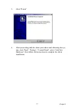
Page 47: ...35 Chapter5 5 a Select Network Adaptors b Click Next 6 a Click Have Disk...
Page 49: ...37 Chapter5 9 a Choose Next 10 a Click Finish...
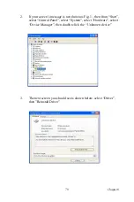
Page 56: ...PPC L126 User s Manual 44 2 a Choose the Driver label b Click Update Driver 3 Click Next...
Page 69: ...57 Chapter7 5 choose Sound video and game controllers click Next 6 Click Have Disk...
Page 71: ...59 Chapter7 9 Click Next 10 Click Finish...
Page 79: ...67 Chapter8 3 Click Yes to accept the agreement 4 Click Next...
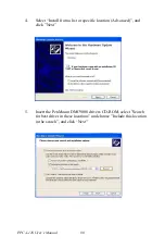
Page 80: ...PPC L126 User s Manual 68 5 Choose the directory then click Next 6 Click Next...
Page 83: ...71 Chapter8 3 Click Yes to accept the agreement 4 Click Next...
Page 84: ...PPC L126 User s Manual 72 5 Choose the directory then click Next 6 Click Next...
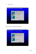
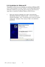
Page 85: ...73 Chapter8 7 Click Finish 8 Click Finish to complete the installation...
Page 97: ...CHAPTER 9 Award BIOS Setup This chapter describes how to set BIOS configuration data...
Page 110: ...PPC L126 User s Manual 98...
Page 114: ...PPC L126 User s Manual 102...
Page 115: ...Appendix B I O Pin Assignments...
Page 121: ...109 AppendixB B 9 PCI ISA Bus connector Slot 1 Figure B 1 PCI ISA connector Side View...
Page 126: ...PPC L126 User s Manual 114...
Page 128: ......


