Chapter 3 Jumper Setting and Connectors.
3.1 Jumpers
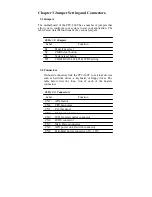
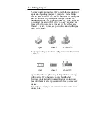
The motherboard of the PPC-L60T has a number of jumpers that
allow you to configure your system to suit your application. The
table below lists the functions of the various jumpers.
Table 3.1: Jumpers
Label Function
S1
Panel type select
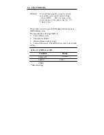
S2 CMOS
clear
button
S3 System
reset
button
JP1
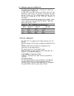
COM2 RS232/422/485 & WDT setting
3.2 Connectors
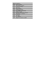
On-board connectors link the PPC-L60T to external devices
such as hard disk drives, a keyboard, or floppy drives. The
table below lists the func- tion of each of the board’s
connectors.
Table 3.2: Connectors
Label Function
CN1 ATX
feature
CN2 CPU
fan
power
CN3 Ext.
flat
panel
CN4
Flat panel connector
CN5
LCD Inverter control connector
CN6 LVDS
connector
CN7 Main
Power
connector
CN8 ATX
power
on/off
switch
connector
CN9
Peripheral power connector (-5V, -12V)
Summary of Contents for PPC-L60T
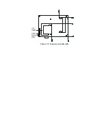
Page 12: ...3 3 Locating jumpers Figure 3 1 Jumper locations...
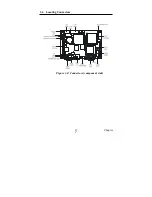
Page 13: ...3 4 Locating Connectors Figure 3 2 Connectors component side 11 Chapter 2...
Page 14: ...Figure 3 3 Connectors solder side...
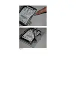
Page 20: ...Fig 4 1 Fig 4 2...
Page 21: ...Fig 4 3 Fig 4 4...
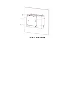
Page 24: ...Figure 5 2 Panel Mounting...
Page 26: ...Figure 5 3 Dimension of Panel mounting holes...
Page 27: ......


