3.9 Watchdog timer configuration
An on-board watchdog timer reduces the chance of
disruptions which EMP (electro-magnetic pulse) interference
can cause. This is an invalu- able protective device for
standalone or unmanned applications. Setup involves one
jumper and running the control software (refer to Appendix
A).
2.21.1 Watchdog timer action (pin 7-10 of JP1)
When the watchdog timer activates (CPU processing has
come to a halt), it can reset the system or generate an
interrupt on IRQ11. This can be set via setting JP1 as shown
below:
Table 2.6: JP1 Watchdog timer action
Pins System
reset*
IRQ11
7-8 closed
open
9-10 open
closed
* Default setting
3.10 USB connectors (CN19)
The PCM-9373 board provides up to four USB (Universal
Serial Bus)
ports. This gives complete Plug and Play, and hot
attach/detach for up to
127 external devices. The USB interfaces comply with USB
specification
Rev. 1.1, and are fuse protected.
The USB interface is accessed through two 5 x 2-pin
flat-cable connec- tors, CN19 (USB1, 2). You will need an
adapter cable if you use a stan- dard USB connector. The
adapter cable has a 5 x 2-pin connector on one end and a
USB connector on the other.
The USB interfaces can be disabled in the system BIOS setup.
Summary of Contents for PPC-L60T
Page 12: ...3 3 Locating jumpers Figure 3 1 Jumper locations...
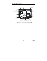
Page 13: ...3 4 Locating Connectors Figure 3 2 Connectors component side 11 Chapter 2...
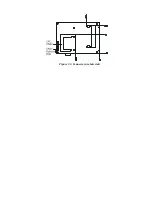
Page 14: ...Figure 3 3 Connectors solder side...
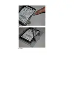
Page 20: ...Fig 4 1 Fig 4 2...
Page 21: ...Fig 4 3 Fig 4 4...
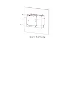
Page 24: ...Figure 5 2 Panel Mounting...
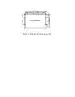
Page 26: ...Figure 5 3 Dimension of Panel mounting holes...
Page 27: ......


