2.2 Installation Procedures
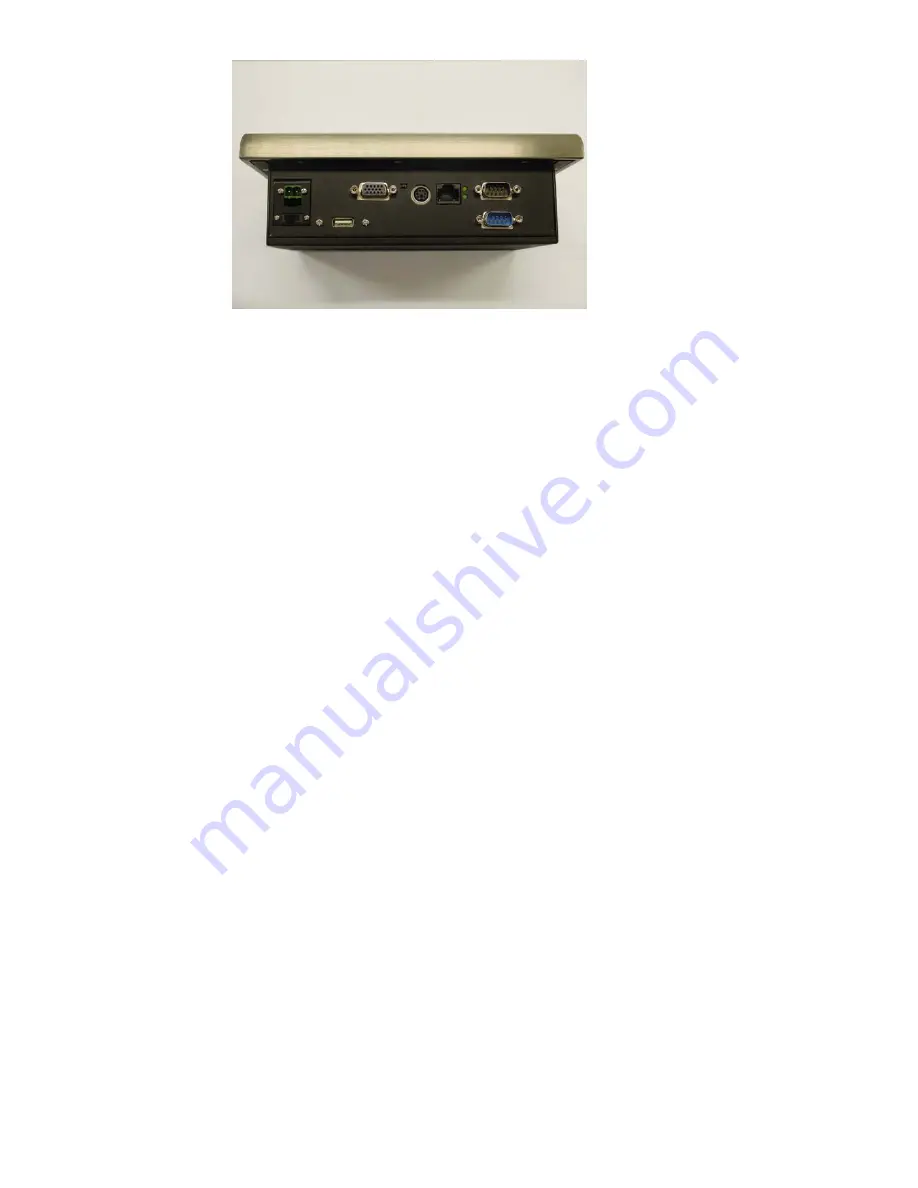
2.2.1 Connecting the power Cord
The Panel PC can only be powered by a DC electrical outlet
12~24 voltage, Max 3.5A). Be sure to always handle the power
cord by holding the plug ends only. Please connect the male plug
of the power cord to the DC inlet of the Panel PC.
2.2.2 Connecting the keyboard or mouse.
Connect the PS/2 mouse and keyboard port on the I/O section of
the Panel PC.
2.2.3 Switch on the power
Switch on the power switch on the rear cover.
2.3 Running the BIOS setup program
Your Panel PC is likely to have been the properly set up and
configured by your dealer prior to delivery. You may still find it
necessary to use the Panel PC’s BIOS (Basic Input-Output System)
setup program to change system configuration information, such
as the current date and time or your type of the hard drive. The
setup program is stored in ready-only memory (ROM).It can
either be accessed when you turn on or reset the panel PC, By
pressing the “ Del” Key on your keyboard immediately after
running the computer on.
Summary of Contents for PPC-L60T
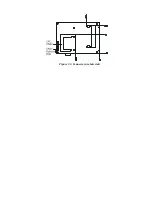
Page 12: ...3 3 Locating jumpers Figure 3 1 Jumper locations...
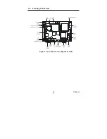
Page 13: ...3 4 Locating Connectors Figure 3 2 Connectors component side 11 Chapter 2...
Page 14: ...Figure 3 3 Connectors solder side...
Page 20: ...Fig 4 1 Fig 4 2...
Page 21: ...Fig 4 3 Fig 4 4...
Page 24: ...Figure 5 2 Panel Mounting...
Page 26: ...Figure 5 3 Dimension of Panel mounting holes...
Page 27: ......


