A
A1
A
2.5
” Disk Tray
Disk #1
A
A2
A
2.5
” Disk Tray
Disk #2
A
A3
A
2.5
” Disk Tray
Disk #3
A
A4
A
2.5
” Disk Tray
Disk #4
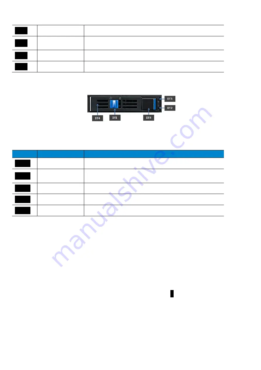
Each Disk Bay has an integrated disk tray that includes a handle, locking mechanism as well as drive LEDs.
Figure
5-5: Disk Tray
Table 1-4: Disk Tray
Item
Element
Description
A
DT1
A
LOCK
Locks the tray in the bay when in the left position
A
DT2
A
LED
Activity LED (amber)
A
DT3
A
LED
Status LED
A
DT4
A
Button
Pushing the button will allow the tray handle to open if unlocked
A
DT5
A
Handle
Tray handle
1.4.1.2 LEDs Details
The SKY-8101D supports an array of status LEDs and buttons at location
B


