SmartMotion ST352
5.8
Description of the rear panel
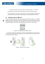
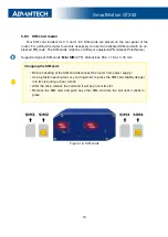
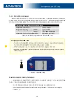
The rear panel contains only four SIM cards readers (
SIM1
,
SIM2
,
SIM3
and
SIM4
), mi-
croSD card reader (
SD
) and
RST
button used to restore default configuration and reboot the
SmartMotion router.
5.9
Description of the front panel
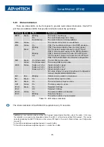
On the front panel is the following:
Caption
Connector
Description
PWR
2-pin
Connector for the power supply
ETH0
RJ45
Connector for connection into the computer network, PoE (only
for PoE PSE or PoE PD versions)
ETH1
RJ45
Connector for connection into the computer network, PoE (only
for PoE PSE or PoE PD versions)
ANT
2x SMA
Connector for main antenna
DIV
2x SMA
Connector for diversity antenna
GPS
SMA
Connector for GPS antenna
WiFi
R-SMA
Connector for WiFi antenna (
only for versions with WiFi
module!
)
USB
USB-A 2.0
Host
Connector for connection of USB devices to the router. Sup-
ports devices with PL-2303 and FTDI USB/RS232 converters.
I/O
6-pin
Connector for connection of the binary inputs and output
Table 9: Front panel description
Figure 12: SmartMotion front panel
14


