13
UNO-410 User Manual
C
ha
pte
r 2
H
ard
w
are
F
un
ctio
na
lity
Digital Output
Output channels 8
Output voltage: 5 ~ 30Vdc
Opto-Isolator response 50 μs
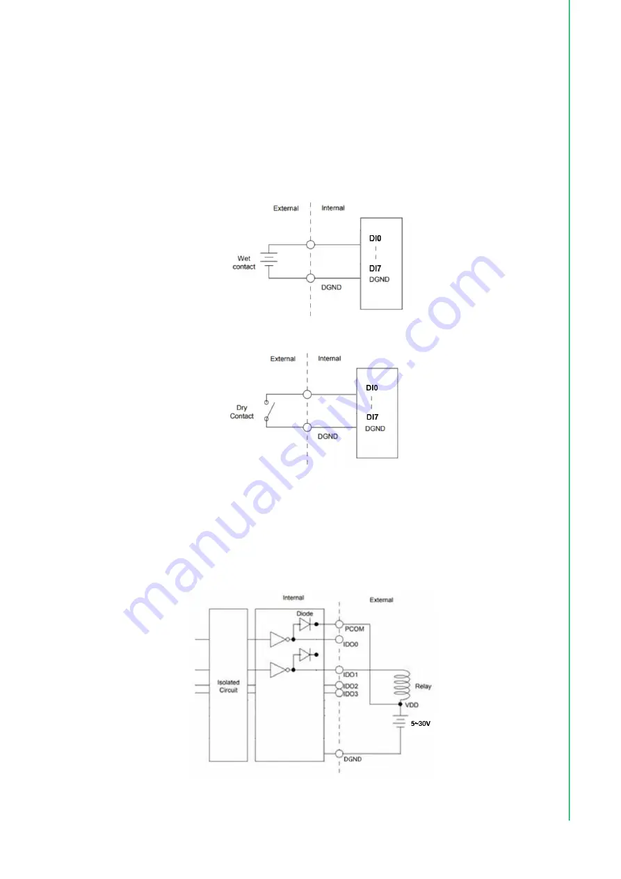
Isolated Digital Input
Each of the 8 x isolated digital input channels accept voltages from 0 to 30 V. The follow
-
ing figure shows how to connect an external input source to the isolated inputs of UNO-
410.
Figure 2.5 Isolated DI Wet Connection Diagram
Figure 2.6 Isolated DI Dry Connection Diagram
Isolated Digital Output
If the external voltage source (5~30 V) is connected to each isolated digital output chan
-
nel and its isolated digital output turns on 5 mA max/ch (UL testing conditions), the
board's current will sink from the external voltage source. The following figure shows how
to connect an external output load to the isolated outputs on UNO-410.
Figure 2.7 Isolated DO Connection Diagram
Summary of Contents for UNO-410
Page 1: ...User Manual UNO 410 Explosion Proof DIN Rail Gateway...
Page 10: ...UNO 410 User Manual x...
Page 18: ...UNO 410 User Manual 6...
Page 30: ...UNO 410 User Manual 18...
Page 50: ...UNO 410 User Manual 38...
Page 51: ...Appendix A A System Settings Pin Assignments...
Page 65: ...53 UNO 410 User Manual Appendix A System Settings Pin Assignments...


