15
UNO-410 User Manual
C
ha
pte
r 2
H
ard
w
are
F
un
ctio
na
lity
Configure the UNO-410 to match the needs of your application by setting switches,
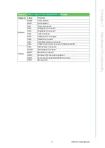
The following diagram shows switch setting definitions:
2.3.1
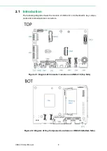
SATA Connector/SATA Power Connector
There are two required onboard connectors that need to connect with 2.5" SATA
SSD/HDD. The location labeled “SATA1” is for SATA connector, and the location
labeled “CN9” is for SATA power connector. (Please refer to User Manual- Chapter
3.3 for installation details and User Manual-Appendix A.5 for pin assignments.)
2.3.2
M.2 Connector
There is one M.2 B Key connector for M.2 cards, labeled “CN15” on the board. This
M.2 interface is a SATA signal co-lay with a USB signal. It will automatically detect
which device you installed and determine the appropriate SATA or USB signal to use.
Therefore, it supports the installation of M.2 2242 (w/SATA signal) or 3042/3052 mod
-
ule (w/ USB Signal). (Please refer to User Manual- Chapter 3.3 & 3.5 for installation
details and User Manual-Appendix A.6 for pin assignments.)
2.3.3
mPCIe Connector
There is one socket for full size PCI Express mini cards, labeled “MINI1” on the
board. Supports iDoor module for diversified applications such as isolated COM port,
Profibus, WLAN GPRS, LTE, and MRAM. Users can install the iDoor easily on the
2nd stake.
2.3.4
Nano SIM Slot
There’s one Nano SIM Slot for supporting LTE function, labeled “CN10” on board. In
addition to install SIM card on “CN10”, users are required to install a LTE Module on
“CN15” M.2 B Key to enable functionality.
Summary of Contents for UNO-410
Page 1: ...User Manual UNO 410 Explosion Proof DIN Rail Gateway...
Page 10: ...UNO 410 User Manual x...
Page 18: ...UNO 410 User Manual 6...
Page 30: ...UNO 410 User Manual 18...
Page 50: ...UNO 410 User Manual 38...
Page 51: ...Appendix A A System Settings Pin Assignments...
Page 65: ...53 UNO 410 User Manual Appendix A System Settings Pin Assignments...


