UTC-W101E User Manual
iv
Safety Instructions
1.
Read these safety instructions carefully.
2.
Keep this User Manual for later reference.
3.
Disconnect this equipment from any AC outlet before cleaning. Use a damp
cloth. Do not use liquid or spray detergents for cleaning.
4.
For plug-in equipment, the power outlet socket must be located near the equip-
ment and must be easily accessible.
5.
Keep this equipment away from humidity.
6.
Put this equipment on a reliable surface during installation. Dropping it or letting
it fall may cause damage.
7.
The openings on the enclosure are for air convection. Protect the equipment
from overheating. DO NOT COVER THE OPENINGS.
8.
Make sure the voltage of the power source is correct before connecting the
equipment to the power outlet.
9.
Position the power cord so that people cannot step on it. Do not place anything
over the power cord.
10.
All cautions and warnings on the equipment should be noted.
11.
If the equipment is not used for a long time, disconnect it from the power source
to avoid damage by transient overvoltage.
12.
Never pour any liquid into an opening. This may cause fire or electrical shock.
13.
Never open the equipment. For safety reasons, the equipment should be
opened only by qualified service personnel.
14.
If one of the following situations arises, get the equipment checked by service
personnel:
a. The power cord or plug is damaged.
b. Liquid has penetrated into the equipment.
c. The equipment has been exposed to moisture.
d. The equipment does not work well, or you cannot get it to work according to
the user's manual.
e. The equipment has been dropped and damaged.
f. The equipment has obvious signs of breakage.
15.
DO NOT LEAVE THIS EQUIPMENT IN AN ENVIRONMENT WHERE THE
STORAGE TEMPERATURE MAY GO BELOW -20° C (-4° F) OR ABOVE 60° C
(140° F). THIS COULD DAMAGE THE EQUIPMENT. THE EQUIPMENT
SHOULD BE IN A CONTROLLED ENVIRONMENT.
16.
If your computer is losing dramatic time or the BIOS configuration reset to
default, the battery has no power.
Caution!
1.
Do not replace power adaptor yourself. Please contact a qualified
technician or your retail.
2.
The computer is provided with a battery-powered real-time clock
circuit. There is a danger of explosion if battery is incorrectly
replaced. Replace only with same or equivalent type recom-
mended by the manufacture. Discard used batteries according to
the manufacturer’s instructions.
Summary of Contents for UTC-W101E
Page 1: ...User Manual UTC W101E...
Page 6: ...UTC W101E User Manual vi...
Page 8: ...UTC W101E User Manual viii...
Page 9: ...Chapter 1 1 Introduction This Chapter briefly introduces the UTC W101E product...
Page 12: ...UTC W101E User Manual 4...
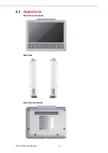
Page 16: ...UTC W101E User Manual 8 2 3 Appearance Front View Terminal Side View Rear View Terminal...
Page 19: ...11 UTC W101E User Manual Chapter 3 Design Requirements...


