AE TECHRON MULTI-AMP CONFIGURATION GUIDE
14
Information subject to change
97-8002465_09-19-14
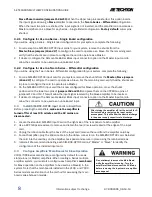
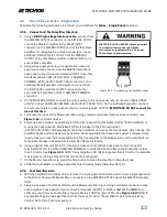
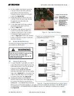
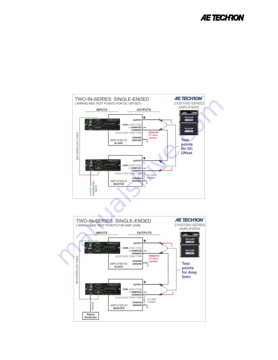
Figure 3.13 – Verifying DC Offset
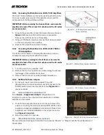
Figure 3.14 – Verifying Amp Gain
3.9.3
Connect Amplifiers and Load
Power down the amplifiers.
1.
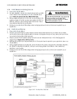
Connect the two output wires leading from the MASTER amplifier’s COM/SAMPLED COMMON connector
2.
and last SLAVE amplifier’s OUTPUT connector to your load.
Power up all amplifiers and allow them to come to the Ready state.
3.
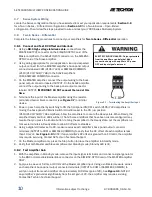
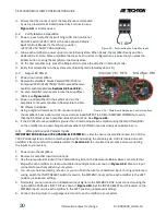
Apply a sine wave of 5Vrms at 100 Hz at the Master amplifier input. Using a voltmeter, measure across
4.
the system load to verify an output from the system of approximately 200Vrms. See
Figure 3.15.
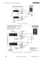
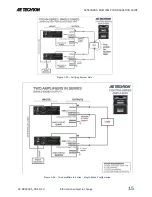
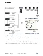
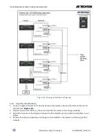
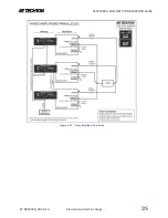
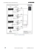
Check the completed system diagrams in
Figure 3.16 or 3.17
to verify proper system setup.
5.
Turn input signal up to the level required for your application.
6.


