AE TECHRON MULTI-AMP CONFIGURATION GUIDE
18
Information subject to change
97-8002465_09-19-14
4.2
Main Board Access
Before operating a paralleled amplifier system, the system first
must be “balanced” to ensure system stability. The balancing
process seeks to calibrate the amplifiers so they operate as
similar as possible. To prevent unwanted current and dissipation
in the amplifiers, each amplifier must have as little offset DC as
possible at no signal. In addition, the gains of the amplifiers must
be as closely matched as possible to keep the outputs from
driving each other when a signal is present.
Balancing of 2100/7000-Series amplifiers requires access to
the amplifier main boards. Note that the main boards installed
in 2100 and 7000 Series models are identical, but the method
for accessing the main board varies between models.
4.2.1
Accessing the Main Board on 2105/7224
Amplifiers
2105 and 7224 amplifiers contain an Access Panel built into
the top cover to allow easy access to the amplifier main board
.
IMPORTANT: Before removing the Access Panel, make sure
the amplifier is turned off for at least 3-5 minutes and the AC
mains are disconnected.
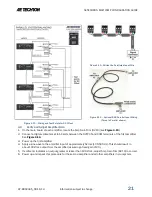
On each amplifier, locate the Access Panel as shown in
1.
Figure 4.5.
Make sure that all 8 screws are accessible.
Remove the unit from its rack, if necessary.
Using a #2 Phillips screwdriver, remove the 8 screws located
2.
on the top and side of the amplifier.
Remove the Access Panel and set it aside.
3.
4.2.2
Accessing the Main Board on
2110/2120/7548/7796 Amplifiers
The 2110, 2120, 7548 and 7796 amplifier’s main board can be
accessed by removing the amplifier front panel.
IMPORTANT: Before removing the Front Panel, make sure the
amplifier is turned off for at least 3-5 minutes and the AC mains
are disconnected.
1
Turn the power to the amplifier “OFF”.
2
Remove the four hex-head screws, located along the left and
right edges of the amplifier front panel.
3
Remove the front cover by pulling straight towards you.
4.3
Disable Gain Controls (2105 and 7224 models only)
In order to ensure the amplifiers in 2105 and7224 Parallel systems
maintain a matched gain while operating, the variable gain controls
located on the amplifier front panels must be disabled. Once
disabled, each amplifier will have a fixed gain of 20. If preferred, the
gain for each amplifier can be fixed at a lower level.
Figure 4.5 – Access Panel Screw Locations
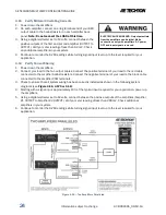
Do not attempt to access the Main Board while
the amplifier is running. Turn the amplifier off
and disconnect the AC Mains before removing
the amplifier access panel. After turning the
amplifier off, let the unit sit for 3-5 minutes to
allow the electrical charge in the power supply
capacitors to discharge.
Figure 4.6 – Gain Control Connection
on Main Board
Do not attempt to access the Main Board while
the amplifier is running. Turn the amplifier off
and disconnect the AC Mains before removing
the amplifier front panel. After turning the
amplifier off, let the unit sit for 3-5 minutes to
allow the electrical charge in the power supply
capacitors to discharge.

