AE TECHRON MULTI-AMP CONFIGURATION GUIDE
97-8002465_09-19-14
Information subject to change
21
4.9
Verify and Adjust Amplifier Gain
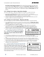
On the main board of each amplifier, locate the Amp Gain Trim (R210) (see
Figure 4.10
).
1.
Connect a digital voltmeter set to AC volts between the OUTPUT and COM terminals of the first amplifier.
2.
See
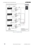
Figure 4.14.
Power up the first amplifier.
3.
Apply a sine wave to the amplifier input of approximately 5Vrms (100-500 Hz). This should result in
4.
about 100Vrms output from the amplifier (assuming a fixed gain of 20).
If voltmeter indicates an output greater or lesser than 100 Vrms, adjust Amp Gain Trim (R210) to correct.
5.
Power up and repeat this procedure for the second amplifier and all other amplifiers in your system.
6.
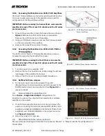
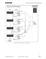
Figure 4.13 – Optional BNC Parallel Input Wiring
(Three in Parallel shown)
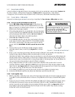
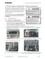
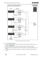
Figure 4.12 – Wiring the Paralleled Input Wire
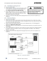
Figure 4.11 – Wiring and Test Points for DC Offset

