AE TECHRON MULTI-AMP CONFIGURATION GUIDE
24
Information subject to change
97-8002465_09-19-14
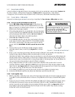
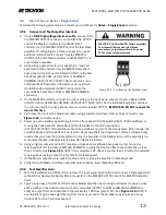
ELECTRIC SHOCK HAZARD. Output potentials
from the amplifiers can be lethal. Make
connections only with amplifiers
’ AC power
OFF and input signals removed.
4.11
Verify Minimal Circulating Currents
Power down the amplifiers.
1.
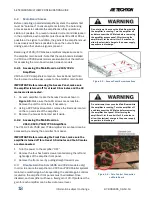
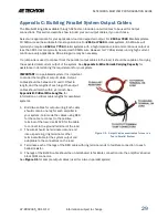
On each amplifier, connect one ring terminal end of your RED
2.
output cable to the ballast resistor on each amplifier back
panel.
Note: Do not connect the LOAD at this time.
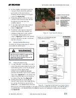
Using a digital voltmeter set to AC volts, connect between the
3.
positive outputs of the first and second amplifier (OUTPUT to
OUTPUT). Verify a meter reading of less than 0.2 mV. Check
any additional amplifiers in your system.
Continue to monitor the DVM readings while turning signal input level up to the level required for your
4.
application.
4.12
Verify Current Sharing
Power down the amplifiers.
1.
Connect your load to the two output cables. Connect the positive terminal of your load to the red cable
2.
connected to the amplifier ballast resistors. Connect the negative terminal of your load to the black cable
connected to the amplifier COM terminals.
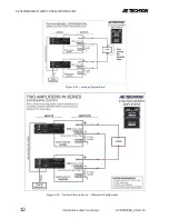
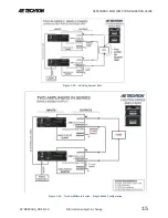
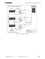
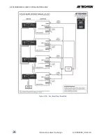
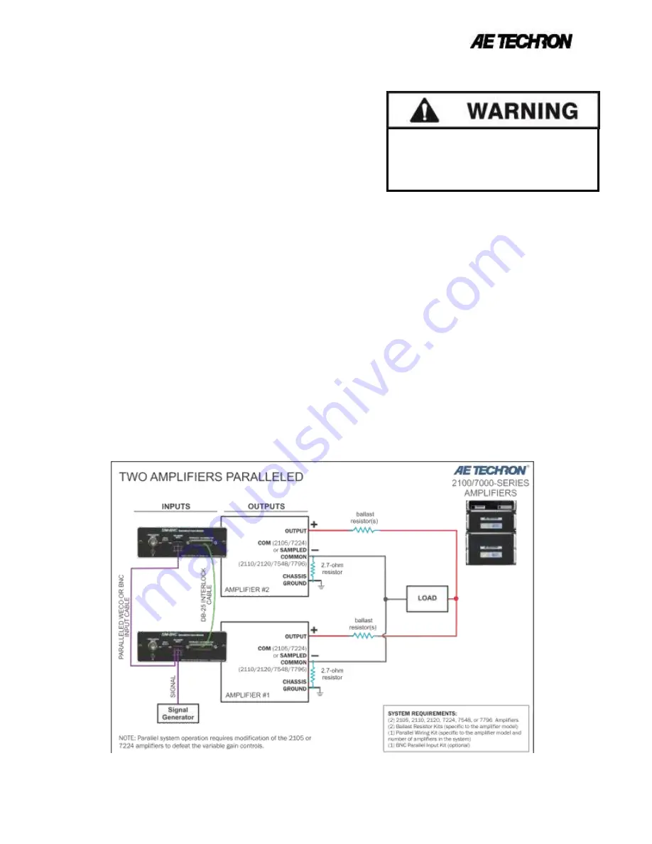
Check to ensure that all system wiring has been correctly installed as shown in the following system
3.
diagrams (see
Figure 4.16, 4.170 or 4.18
).
Starting with a signal input approximately 10% of the typical input required for your application, power up
4.
the amplifiers.
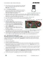
Using a digital voltmeter set to AC volts, connect between the positive outputs of the amplifiers (Amplifier
5.
#1 OUTPUT to Amplifier #2 OUTPUT). Verify a meter reading of less than 200 mV. Check additional
amplifiers in your system.
Continue to monitor the DVM readings while turning signal input level up to the level required for your
6.
application.
Figure 4.16 – Two Amplifiers Paralleled

