AE TECHRON MULTI-AMP CONFIGURATION GUIDE
97-8002465_09-19-14
Information subject to change
3
List of Figures
Figure 1.1 – Maximum Continuous Output in 7000-Series Multi-amp Systems .................................................. 4
Figure 3.1 – Two in Series: Single-Ended vs. Differential ........................................................................................ 7
Figure 3.2 – SIM-BNC-OPTOC card jumper locations............................................................................................... 7
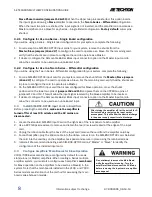
Figure 3.3 – 7224 Amplifier Access Panel Screw Locations ................................................................................. 9
Figure 3.4 – Master/Slave Jumper Locations .......................................................................................................... 9
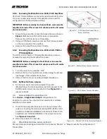
Figure 3.5 – 7224 Output Terminal Resistor ........................................................................................................... 9
Figure 3.6 – 7548/7796 Output Terminal Resistor ................................................................................................ 9
Figure 3.7 – Terminating the Amplifier Input ......................................................................................................... 10
Figure 3.8 – Verifying DC Offset .............................................................................................................................. 11
Figure 3.9 – Verifying Amp Gain .............................................................................................................................. 11
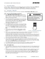
Figure 3.10 – Verifying System Gain ....................................................................................................................... 12
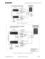
Figure 3.11 – Two Amplifiers in Series – Differential Configuration .................................................................... 12
Figure 3.12 – Terminating the Amplifier Input ....................................................................................................... 13
Figure 3.14 – Verifying Amp Gain ............................................................................................................................ 14
Figure 3.13 – Verifying DC Offset ............................................................................................................................ 14
Figure 3.15 – Verifying System Gain ....................................................................................................................... 15
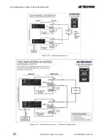
Figure 3.16 – Two Amplifiers in Series – Single-Ended Configuration ................................................................. 15
Figure 3.17 – Three Amplifiers in Series – Single-Ended Configuration .............................................................. 16
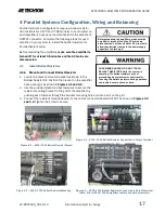
Figure 4.1 – 7224 Ballast Resistor Mounting ........................................................................................................ 17
Figure 4.2 – 7796 Ballast Resistor Mounting ........................................................................................................ 17
Figure 4.3 – 7224 Ballast Resistor Connected to Output Terminal ..................................................................... 17
Figure 4.4 – 7796 Ballast Resistors Connected to Output Terminal ................................................................... 17
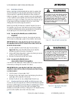
Figure 4.5 – Access Panel Screw Locations ........................................................................................................... 18
Figure 4.6 – Gain Control Connection on Main Board .......................................................................................... 18
Figure 4.7 – Gain Control Pin Settings .................................................................................................................... 19
Figure 4.8 – Connecting for Balancing (Four in Parallel shown)........................................................................... 19
Figure 4.9 – Terminating the Amplifier Input ......................................................................................................... 20
Figure 4.10 – Main Board Balancing Control Locations........................................................................................ 20
Figure 4.11 – Wiring and Test Points for DC Offset ............................................................................................... 21
Figure 4.12 – Wiring the Paralleled Input Wire ...................................................................................................... 21
Figure 4.13 – Optional BNC Parallel Input Wiring (Three in Parallel shown) ...................................................... 21
Figure 4.14 – Wiring and Test Points for Amp Gain ............................................................................................... 22
Figure 4.15 – Wiring and Test Points for Gain Matching ...................................................................................... 23
Figure 4.16 – Two Amplifiers Paralleled ................................................................................................................. 24
Figure 4.17 – Three Amplifiers Paralleled .............................................................................................................. 25
Figure 4.18 – Four Amplifiers Paralleled ................................................................................................................ 26
Figure A-1 – Wire Current-Carrying Capacity Chart ................................................................................................ 27
Figure B-1 – Critical Wire Lengths in Parallel Systems .......................................................................................... 28
Figure C-1 – Output Cables constructed for use in a Two-in-Parallel System ...................................................... 29
Figure D-1 – DB-25 Cable Wiring for a Four-in-Parallel System ............................................................................ 30
Figure E-1 – 7224 Access Panel Screw Locations ................................................................................................. 31
Figure E-2 – Master/Slave Jumper Locations ........................................................................................................ 31
Figure E-3 – Output Terminal Resistor .................................................................................................................... 31
Figure E-4 – 7548/7796 Output Terminal Resistor .............................................................................................. 31
Figure E-5 – SIM-BNC-OPTOC, Factory Default Settings ........................................................................................ 32


